As of Wednesday, April 28th we got her started. So on Saturday, May 1st, I decided to start tidying up the electrical by wire tying things in place. I also want to remove the alligator clip that is being used as a ground. This is where things take a turn for the worse. Additionally, this is where hindsight is twenty-twenty. So I find a nice place for the ground on the transom. Suddenly, it won’t start again (Fuel Pump Won’t Energize). Put it back on the alligator clip, then it starts. Move the ground to the block, won’t start again. Here we go again. No codes on the SmartCraft gauges other than the trim limit. Put it back on the alligator clip, now it won’t start. So we know we have MerCruiser Electrical Gremlins.
The MerCruiser Electrical Gremlins Continue
So I work on chasing and probing connectors, and about four hours later, It now starts. I call it quits for the day. I will tidy things up tomorrow. So on Sunday, it starts before I start wire tying things up. After I start wire tying things up it won’t. Now I keep working on trying to figure out why it keeps acting like this. So it seems from 12:30 to 5:30 It won’t ever start, and it’s related to fuel delivery. 5:30 Rolls around and it starts again. Now I’m thinking this has to do with a wire, splice point, or connector.
Take a step back from the MerCruiser Electrical Gremlins
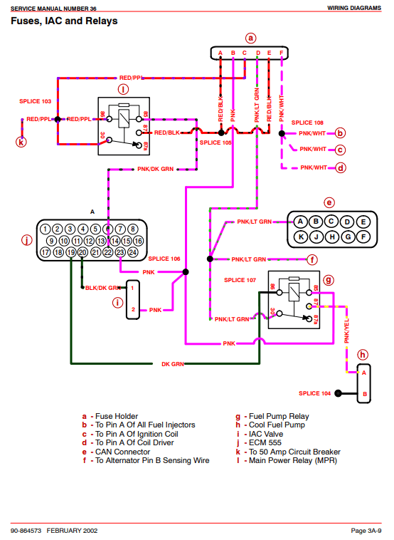
I quit for a bit to review a few wiring diagrams and go eat. About two hours later and take another crack at it. I wire tie the main harness that goes to the ECU and it won’t start again. So, I start probing the main power relay. Here I find there is no ground here. Additionally, I find the purple with black wire which should be to ground according to the ECU pinout.
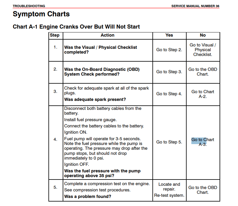
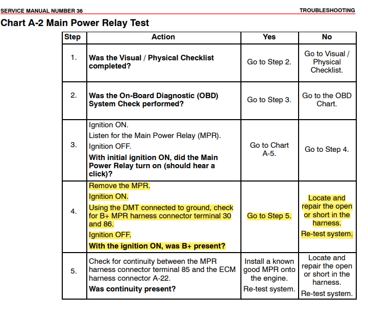
So following the chart, which I should have never had. It suggested that I go to fuel system electrical test. This is a bit misleading because what I’m going to find out in a few is that if I had just read to the next section A-2. It’s going to lead me to the root cause, which is the Main Power Relay and the related ground Ground on pins 85 and 22. I just happen to stumble upon this looking for the right voltages and not seeing them on two of the relays. I have positive voltages on the MPR, but no ground. Additionally, that is step 5!
It’s a bad ground on the connector to the ECU!
So Terminal 85 to pin 22 reveals that there is no contact. as unwrap the wiring to trace the wire, I notice that someone has probed this wire before. A little background, the outfit that worked on this board said there was some sort of intermittent electrical issue. I bet it was this! All the relays look fairly new too. It shows continuity up to the back of the harness and not at the pin that goes to the ECU. I pull on the Pink and Black wire from the back of the connector and it comes out. It’s corroded and broken. I push it in and hear a click. Then I turn the ignition switch on and I hear the fuel pump run. I toggle it to start and it starts! I turn it off. Problem solved! Now, the bigger question is what the heck is the connector!
Pin_22_Detail 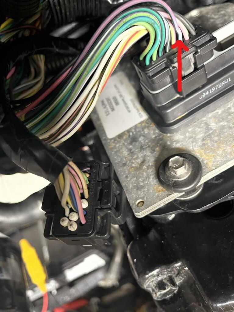
Pin_22_MPR
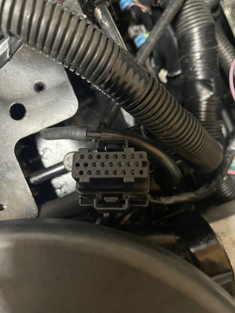
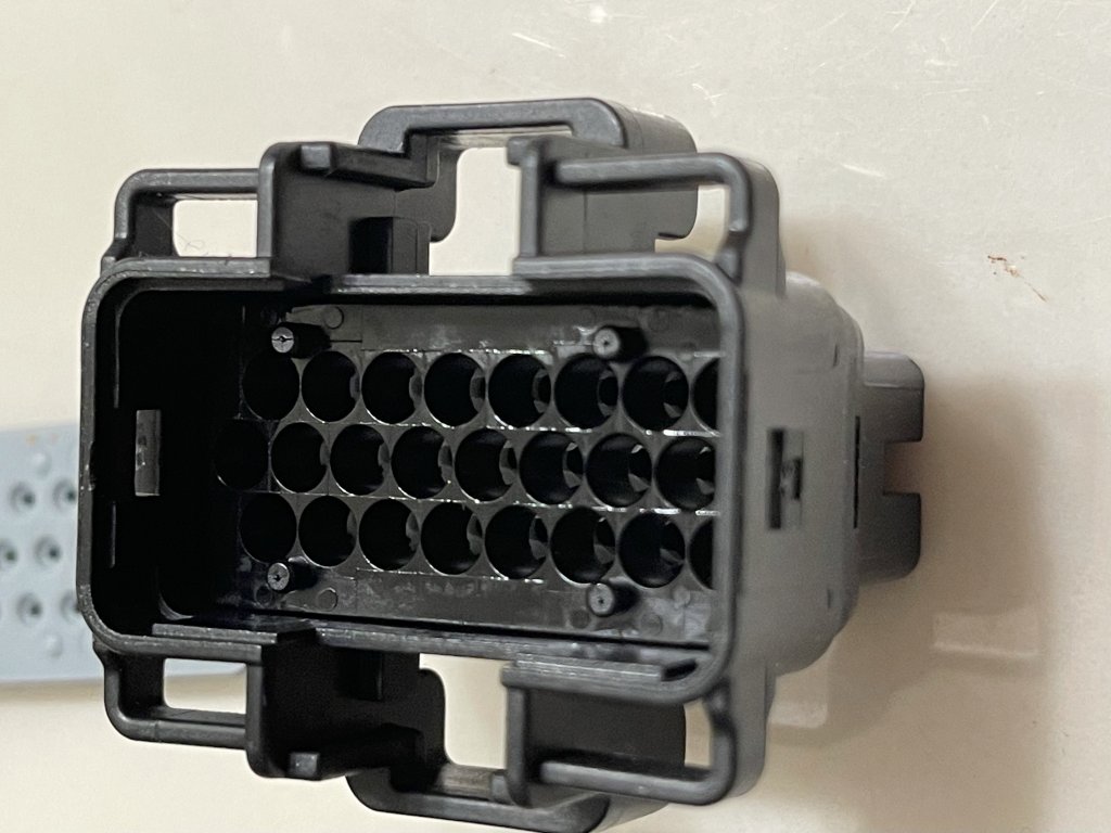
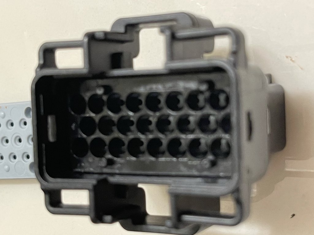
What is this connector?
So we have narrowed it down to this connector. So the short answer to the question is it’s an ECM 555 B Connector. The disconnected connector is an ECM 555 C Connector. The connector itself is about twenty-eight dollars. The pins are about three dollars for ten. You can get the pins and connectors from them here. They seem to have a wide variety of connectors. These may be the folks I look to reflash the ECM since this is a 5.0 and not a 5.7. It’s odd because the hull ID shows that she originally came with 5.7. Who knows what has been done to this poor boat. It’s in good hands now!
Repairing the ECM 555 B connector
So I order the ECM 555 A/B connector. About a week later it arrives. I want to have this in hand to see how it comes apart. it’s a Tyco Connecter with 24 pins. I start the process of replacing the bad pin. Firstly, I remove the wire retention at the back of the connector by Depressing the Black tabs and Pry the retainer and slide it back. The Pin is locked in by a sliding mechanism. you can see it in the bottom pictures step 5 & 6. push it till it clicks. This will release the pins. What I notice after I remove the retention is there are more than a few pins that are corroded. Basically pins 24-20 have to be replaced. Additionally, they are a crimp-style connector. I will need my 6x glasses to do this work!
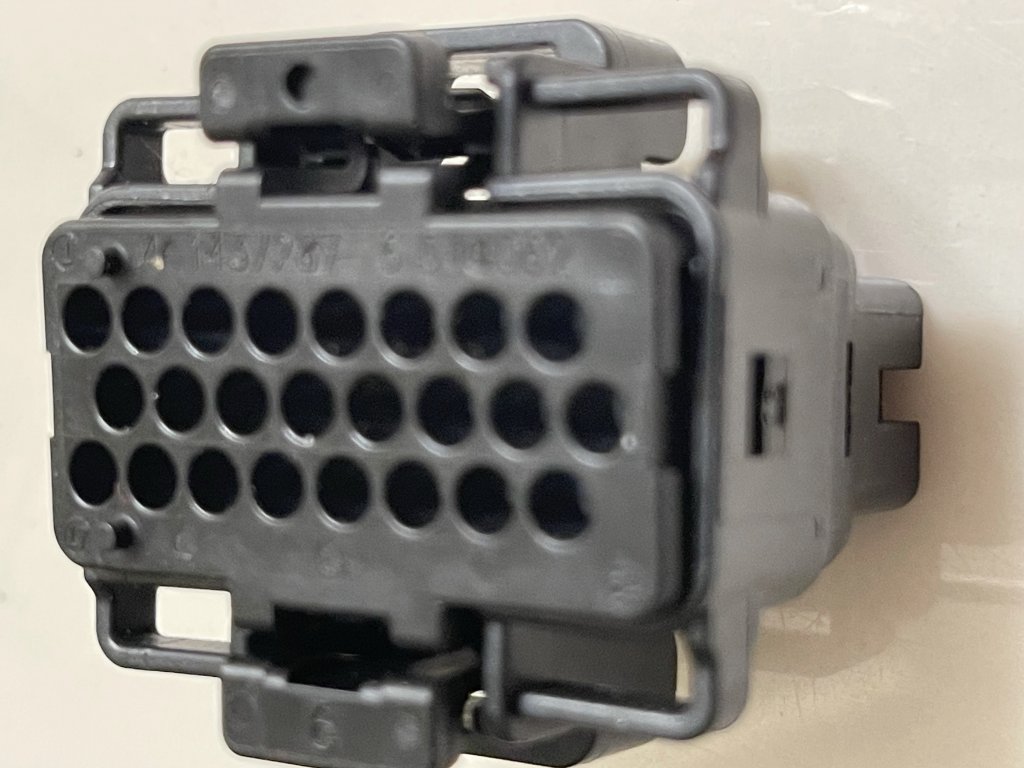
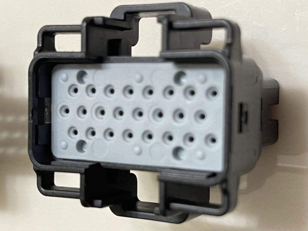
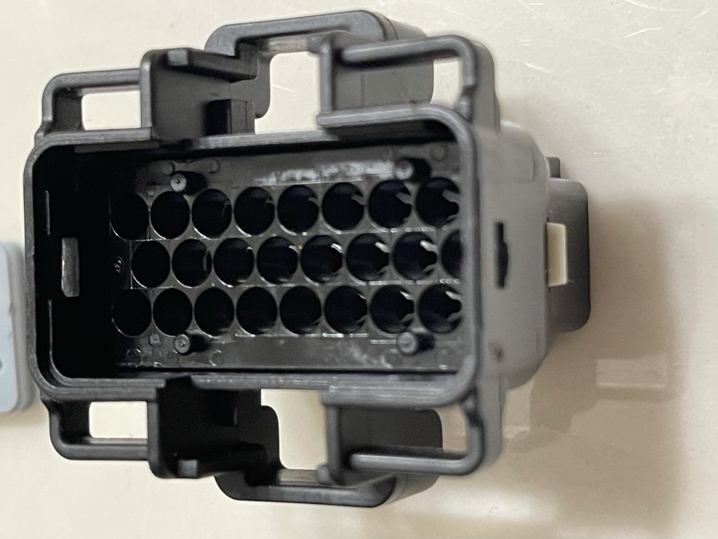
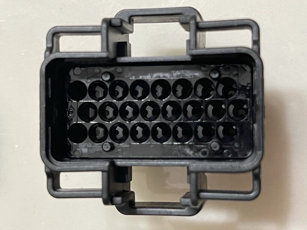
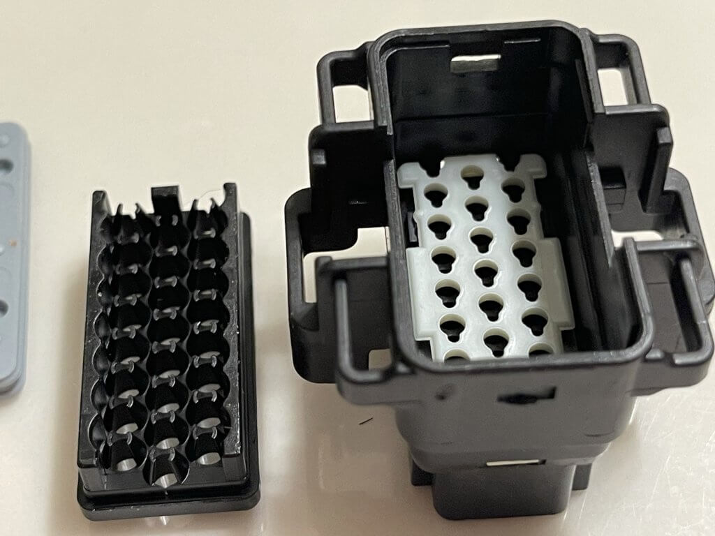
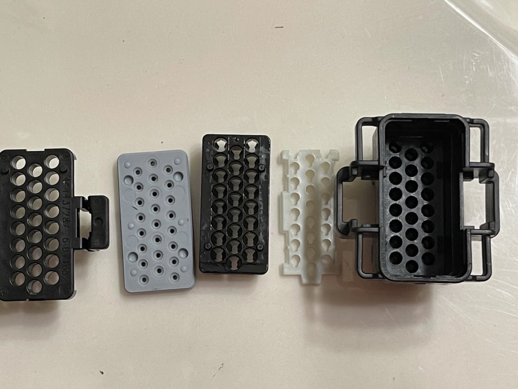
Above is the ECM555 A Connector, not the B connector I’m working on. I step through the process of how the connector is assembled in these pictures. Hopefully, this is helpful in showing you how these connectors come apart?
To get the pins out you can wiggle them out while pulling back on the wire or use a pick and push them through. There is a pin retaining mechanism beyond the white locking tab. I do these one at a time and move them from the old connector to the new one. I made a mistake when I put the new pins in and had to do this twice. the locking mechanism is a bit tricky. When you slide the new pins or reseat the old ones you need to make sure they click into place all the way to the front. After I repaired the connector she seems to not exhibit an issue related to the fuel pump. She starts without an issue! She will exhibit other Gremlins as I proceed along.
Keep in mind this boat sunk and clearly was powered on when this happened. The main wiring harness is around a thousand dollars. It’s virtually impossible to find this harness anywhere used. I may keep my eyes open for one. I need to find a marine salvage yard. So far I’m into this boat for about three thousand in parts and tools. That is still a deal, minus my labor! So at this point, I feel I resolved most of the MerCruiser Electrical Gremlins
Hook up the thru hull exhaust
Lastly, I will rewire the thru-hull exhaust and connect it to the manifolds. I’m going to shortcut things here and reuse the gaskets by scraping them down and using red RTV to seal them to the flanges. I have a feeling they make these gaskets to lessen the chances of a leak due to improper preparation and the related humidity when using silicone. The boat is out of the water so I might as well see if this will work. I will find out later this will save me when about four hundred dollars when I find out that there is a leak on the flapper on the Corsa Exhaust. At last, it’s time to hook her up to the water ears and see if she runs more than a few seconds and does not ingest water.