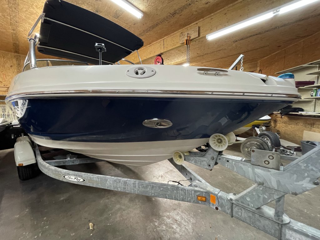
We are starting some of the easy stuff related to the 210 Select electrical rewiring. First, we are going to focus on the horn, docking lights and navigation lights. They are at the front of the boat and I need to determine if I have to re run new wiring. Up to this point I have been primarily working on the engine. I spent several hours cleaning out cylinder head bolt holes related to last re-powering effort. I also am painting all the flaking and peeling paint. I’m doing a lot of this in parallel.
Table of Contents
What I’ve done so far to 210 Select Electrical Rewiring
So, I have been trying to remove as much of the old wiring that is not related the to operation of the boat as part of the 210 Select electrical rewiring effort. I have removed all the old radio and speaker wiring. This is not essential to the boat running. Additionally , I’ve also removed the mess of dash and the the wiring. The SmartCraft gauges are out too.
Inspecting the overall condition of the Sea Ray 210 Electrical
I’ve inspected the. Main wiring harnesses and helm-related electrical components. First, the main wiring harness that runs from the helm to the stern seems to be in good shape. That’s a plus. Additionally, it looks like there are a new fuse block and switches. That’s good. Second, the work that’s has been completed is half done. Below is the plug to the Mercury SmarCraft (Tachometer). The Guage is junk from what I can tell. The power lead is a bit gone!


What we know up to this point!
We know the work to 210 Select Electrical Rewiring completed so far is minimal. The approach was to get the boat to start and no more. This has a plus side and an minus side. The plus side, the wiring diagrams are confined to three pages more or less. This make things a bit more manageable. The minus side, the wiring is run before the boat is put together. Additionally, the front of the boat is pretty much inaccessible to work on anything up front. This includes the Horn, Docking Lights and navigation lights. To accommodate this nuance, I removed the front speakers for now so I can get access to the wiring harnesses. Lastly, a lot of the wiring is corroded due to this boat sinking in saltwater. I have included the electrical which is part of the 2007 Sea Ray 210 Select User Manual. See the link below. It the very last pages by the way.
Wiring the Horn
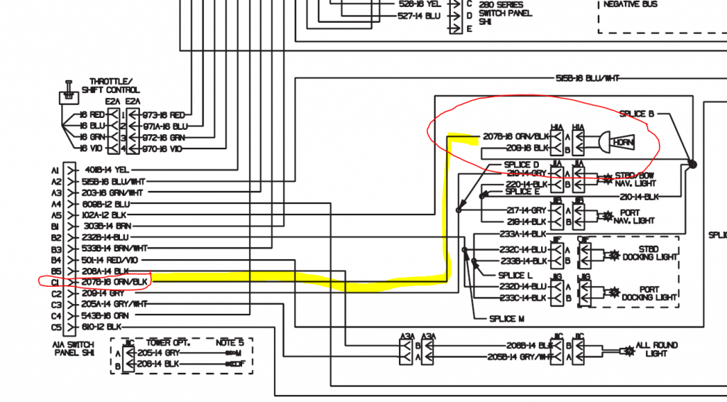
Initially, I thought that I was going to have to rewire everything. This may not be the case. When I first started trying to solder to the orange and black wire to the horn, I could not because it was too corroded. Second, on the starboard side someone cut all the wires to the horn ,and docking lights. Not the same on the Port side of the boat. So not worried about length, I cut back the orange/black and black wires. The logic was to either find a good section of this wire or run a new one to the helm. The horn is not a Sea Ray Specific part – Aqua Signal 84401-7 Dual Tone Electronic Hidden Horn – White
Much to my surprise, after cutting back a couple of inches, I found nicely coper colored wires. To ensure I’m dealing with a good run. I checked continuity and resistance between there and the connector in the Helm This is a AIA Delphi METRI-PACK 280 Series Wire Harness SH2. Much to my surprise it was less than two ohms resistance. I think I can deal with that! So I spliced on a short sections of wires for the hot (Orange/Black) and Ground. Heat Shrunk and Electrical tapped the splices and then added a two pin water proof connector to the horn and wired it up!
Testing the Horn
So to accomplish this, I went old school. I have kept the Perco switch off. First, I don’t need something going horribly wrong. Second, so what I did is hook up a 12V battery out of one of my Sea Doo’s to the negative and positive side(s) of the fuse blocks using fused alligator clips.
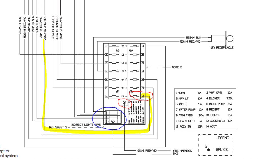
Blue is where I connected the negative Jumper, and right above it to the middle right the positive jumper. Highlighted and also and in red to the very eight is the fuse block horn circuit fuse and circuit.
What is actually working
So much to my surprise, the Cabin lighting, Dash lighting, Bilge Pump, Bilge Fan and Horn are all working. This might not be as bad as I thought. but I’m not holding my breath! On to the Docking Lights!
Rewiring The Docking Lights
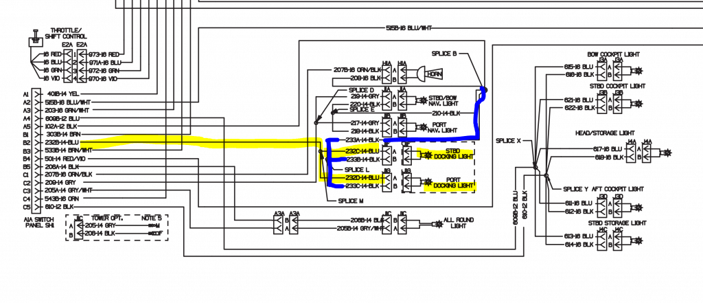
So we were successful getting the horn to work so its now on to the docking lights. Take a look at the above Starboard Docking Light Schematic. They are identified by 232C-14-Blue and 232D-14 Blue. First, I run a long lead from the blue Starboard connector and check for continuity on 232C-14. Secondly, I check for continuity on 232B-14 and the Black Starboard connector. Thirdly, I test for continuity between the black and blue connector. There should be none! Instead, it blows the fuse in my multimeter and that’s the end of the day until I can get a new fuse. I may use my probing tool later this week instead of the multimeter.
The docking lights are a bit confusing
So, there is bit of confusion around the what I’m seeing in the schematics. Firstly, It looks like there are two wires that are spiced together. Secondly, if you look there appear to be a port and starboard docking set of switches. Clearly, this is not the case. I have a single switch. There is a positive and negative power source, as well as a switched docking lights.
I want to buy a new horn for my husband’s SeaRay 210. What would be the best one to get?