This is the process of me performing a Corsa Exhaust Solenoid Replacement and Dual Coil Actuator Replacement. This was one of the last remaining pieces I had to address. I was able to do this by doing a bunch researching. Below is a picture of the old solenoid and Dual Coil Actuator. There is nothing here that I’m going to be able to use from the old solenoid. The Dual Coil Actuator I removed from the Solenoid harness is bad also, I assume. Before removal of the harness & Solenoids I did some probing before removal. The circuit is not working properly. Originally there is four-wire solenoid, I ordered a three wire replacement one, off of Amazon to replace it. The reasoning behind this will become more clear as I proceed. I hope this helps all of you who may run into this issue with a Corsa Thru Hull exhaust.


Corsa Exhaust Solenoid Replacement & Actuator Removal- Process
So the Corsa Exhaust Solenoid Replacement using the existing Corsa wiring harness is fairly straight forward. Firstly, I’m going to use a three wire solenoid instead of a four wire solenoid and make some modifications to get this to work properly. What I’m going to use is the following pieces to rebuild the harness. There are some nuances of replacing the factory actuators with the ones off of Amazon. Keep in mind I replaced the Corsa actuating mechanism prior to this exercise. That in itself is a learning exercise.
- One -Existing Corsa Wiring
- Two –Three Wire Solenoids
- One – Timer WIFI 10 AMP 6V 12V 18V 24V TIME ON OFF DELAY CONFIGURABLE
- One – 30/40 AMP Relay Harness SPDT 12V, 5-PIN SPDT Relays
There is about a hundred dollars worth of parts to complete the conversion including the Solenoids. This is about a third to a fourth of price of the harness and the Solenoid’s. Now this is going to require some re-engineering. I’m up for the challenge of doing a Corsa Exhaust Solenoid Replacement after doing hours of research.
Corsa Exhaust Solenoid Replacement and Dual Coil Actuator – Current State Function
So let me give you some background here about the Corsa Exhaust Solenoid Replacement and to how I ended up here. Firstly, the Solenoids are beyond repair. The have rust preventing them from actuating. Secondly the Dual Coil Actuator With Timing Circuit Solenoid Actuators function are questionable. Next to start, I did some probing of the exiting Corsa wiring harness. While they were still on the boat. I tested them and the Dual Coil Actuators were electrically engaging the pull circuit upon turning the ‘Perco’ to on. The switch on the dash does not appear turn them on or off as it should. What the switch does do is provide power to the red hold wire in the harness but that is it. So I know that part of the wiring is good. Further more, the hold circuit can not pull the Solenoid closed.
Corsa Exhaust Solenoid and Dual Coil Actuator With Timing Circuit
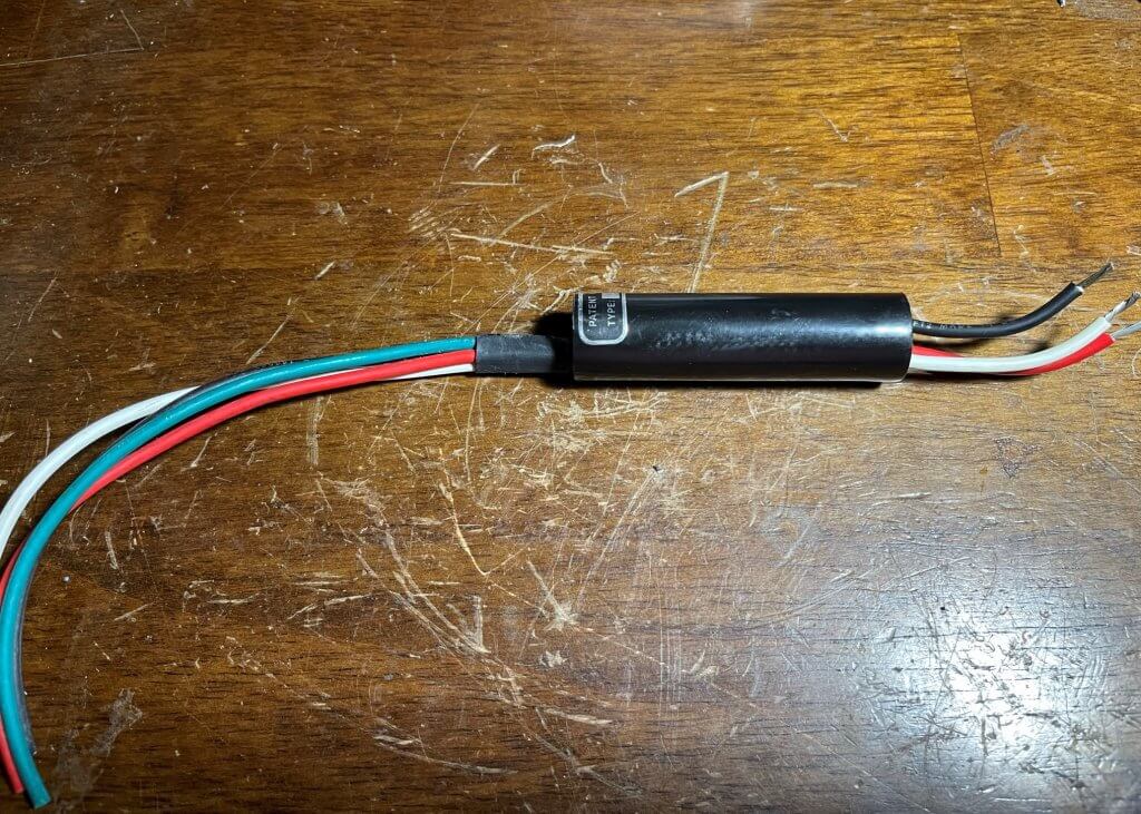
In the picture above is one of the dual coil actuators with timing circuit. From the wiring harness to the dual coil actuator it has three wires at the Dual Coil Actuator four wires that go to the Solenoid itself. You can see in the table blow the three wires I’m describing function to the right below. So the reason why this does work as I would expect. Currently there is a ground (Black), positive main power (White) and Dashboard Switched (Red/Orange). Once the power is applied from the Perco it will activate the Solenoids regardless of the dash switch. I don’t know if this is some sort of wiring snafu or because of the bad Dual coil actuators ?
- Red – Dash Switch – Power Positive (Hold/Latch)
- White – Power Starter – Splice from Power (Pull)
- Black – Ground
Corsa New Style Three Wire Harness
You can see from the new wiring harness what the new style harness. Even in this diagram the I can tell that when power is applied to the circuit the Solenoid’s will activate and the dash switch has no effect. There is also no latching device so I assume its being done elsewhere.
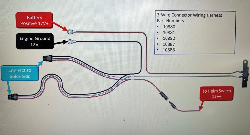
What I can tell you is for this to activate the circuit via the switch I need to switch either the positive power or the ground. I found this in another article about an older Corsa Two Wire Solenoid. This is further complicated by the fact that Corsa main harness ties the main power from the Starter Solenoid to the white pull actuator on the Solenoid. The Thru Hull Exhaust Solenoids can not stay on constantly or they will burn up. The White pull wire has to be trigged off within one to three seconds of applying power to the circuit. Additionally, the the hold needs to be triggered by the switch on the dashboard to hold and latch the Solenoid closed. None of this appears to happen. So lets proceed!
Dual Coil Actuator With Timing Circuit Solenoid Actuator – Details
So I did a bit of research on this device the (Dual Coil Actuator With Timing Circuit Solenoid Actuator). It’s basically does what I thought it does. its a time delay device in a water proof connector. There is a number on the side of the device which I looked up, and pulled the Patent Information. Its by Woodward Controls Inc. and It uses transistors to basically accomplish what I’m trying to do here. It’s clearly not elegant as the exiting Dual Coil Actuator’s. Regardless, this should work, I’m just using an external relay. I tried testing the output by applying power, ground an trigger and purchasing two four wire solenoids for testing. the pull circuit stayed engaged the entire time. So, the Dual Coil Actuators must be defective. There is no easy way to repair them.
Dual Coil Actuator With Timing Circuit Solenoid Actuator – Removal
To start, you will need to remove the old harness from the boat and the solenoids if you are dealing with the situation I’m dealing with of bad solenoids and bad Dual Coil actuators. Next, I had cut out the Dual Coil actuating device. This is some sort of latching device. Pictured above is the barrel actuating device we are going to remove. These actuators are around a hundred dollars a piece with the solenoid and actuators if you decide to go that route. I’m not, I’m going a different route and replacing and reconfiguring it for proper operation in my situation.
What I will do is resplice the wires the new three wire Solenoids back to the male connectors and shrink wrap them. It takes about twenty minutes to complete this for both the solenoids. Below is how the wiring needs to be to connected the new three wire Solenoids. Below is a comparison of old vs new and the related wiring.
- Red to Blue (Latch / Hold Positive)
- White to White (Pull Positive)
- Back to Black (Ground)

Woodward Dual Solenoid Actuator Circuit – Replacement and Wiring
So, after I attach the new Solenoids to the harness, I will need to start addressing the pull and hold/ latching circuit. What I’m going to do here is cut the pull circuit white wire (Red Starter to White) and tie it to a relay. You will need to cut open the existing wiring harness to get access to these wires. Its the part of the harness that has the 50 AMP breaker. It ties the main power from the starter relay to the white pull wires. They “Y” from here. I’m going to use the 30/40 AMP Relay SPDT and a Wi-Fi configurable Timer to accomplish this the switching of the power on the white wire or pull circuit. You could purchase a timer that is not Wi-Fi configurable, but there was not a huge cost savings and I like the ease of configuration.
Below is a diagram of the timer. In the diagram, the load is my relay that I will use to activate for three seconds then shut off using the Wi-Fi Timer.


Corsa Exhaust Solenoid Pull & Latch Circuit – Operation
So, in theory I’m wiring this up so that when the thru hull exhaust switch is turned on on the dash (Orange) , it powers the hold circuit and and turns on the Wi-Fi timer. The hold power in the Solenoid is not powerful enough to pull the plunger on the Solenoid in. The Wi-Fi timer in turn powers up the relay which closes the circuit for three seconds (Configured) to the high current pull circuit (White) and then turns the power off to the relay, which leaves the hold/latch in place. When the switch on the dash is turned off, it removes the power to the hold/timer and shuts down the circuit. This is how it should work in theory from, lets see if we can get to reality?
Corsa Exhaust Solenoid Pull & Latch Circuit – Rewiring
To start as mentioned prior you will need to cut the red wire that is tied into the white wire(s) in the main Corsa wiring harness. Leave enough lead to re-connect to these wires. You will have an extra wire. I put on some quick connectors on the Wi-Fi timer and the relay. Second, with the Red 16 Gauge (Switched) Wire from the Corsa wiring harness we will power the timers Red connector, turning the timer on and providing Red holding wire on the Corsa harness. All the grounds are tied together. The only exception is ran the timer ground separate and no in the the Corsa harness.
Next, on the Timer you will need three wires. Red from the through hull exhaust to trigger the timer. Yellow from the Timer to the white wire on the relay to Pin (86) and the black Pin (85) to ground. I ran the black from the timer to a separate ground. now you will need to wire the blue Pin (30) to the main power (Starter Relay) and then run the Pin 87 to the white wire. I solder all these connection and use heat shrink tubing to keep these safe from the elements.
Corsa Exhaust Solenoid Pull &Latch Circuit – Rewiring
So you can either do this on the boat or on the bench. I chose the latter. Now power up the timer by connecting the positive, negative battery cables and trigger wire from the Corsa Wiring Harness. Next , short the white wire to ground then remove it. There is a Blue light that should illuminate. Now connect to the the Wi-Fi timer via Wi-Fi. You will need to configure this timer function 2 – Interval on. We are not using a trigger. Additionally, We will be setting T1 to 3 Seconds. Keep in mind you can not keep the Wi-Fi trigger for the timer to function. You can though test the function of the timer on and off through the web interface. Make sure the relay actuates and deactivates from the web interface. Lastly, now remove the power.
Corsa Exhaust Solenoid Pull & Latch Circuit – Testing


Now, power up the circuit by applying power to the main power feed , hold/trigger wire and make sure the the pull circuit actuates. Secondly, you should hear the click of the relay going on and then off. The hold circuit should still have power and the Solenoids should remain actuated. Remove the trigger, and the Solenoids should retract. In may case this worked perfectly, so I buttoned everything up and put everything back on the Piperella. Lastly, I tested it using the switch. One change I’ did make is move the main power from the Starter Solenoid and moved it to the main power buss positive feed.
One thing to keep in mind I used two circuits to power my equipment on the bench to ensure the pull circuit had enough current and that the hold circuit was working by measuring the amperage output. I hope this help all of you ? This took me days of research, planning, and testing.
So the last part is to install this back on the boat. I have added a few pictures to show you how it looks installed on “Piperella” The Green Arrow Points to the Wi-Fi Timer. Red is the external relay and Purple are the quick connectors I used so the individual components can be removed easily.
What’s Next ?
So there are a few things we need to do to “Piperella” electrical wise. We need to address the lack of a fire suppression system and the related wiring. Additionally, we need the Stereo to turn on when the ignition switch is on not the “Perco”. I Think the pressing item will be the Fire Suppression system, so that will be next.
What is the Corsa part number for the time delay switch and do you know where I can get them?
Also what is brand and part number of the new timer you used, I could only fond a 5 amp one
I used a WiFi timer module, it has a link, to buy it . Use it in Combination of the external relay. The 5 amps is sufficient to trigger the relay cool , use the N/O and the 12v positive to activate the solenoid. Reach out to me if you have any questions.