So we are about eight months into 2022. First, we need to get back to starting the Autopilot install and the first step is to get the RayMarine Rotary Rudder Transducer installed. Secondly we worked out getting our fuel tanks to show up on the RayMarine MFD by using a YDTA-04N. It was not worth the hassle of trying to figure this out on the Arduino. Additionally, we have been back on the water and enjoying the Summer with the boats. We have been enjoying both the Sea Ray 210 and the Silverton 352, with minimal issues. One of the major things I still dislike is a lack of a rudder indicator on the Silverton. Counting revolutions and a piece of tape is just not going to cut it. Especially, having to do maneuvers under stress or scrambling.
Additionally, I was able to install a rudder transducer and indicator on the Sea Ray. It was actually quite simple. It has made docking, rafting up and maneuvering much easier. So, we pick up where we left off about five months ago, when we were researching what components we need.
Table of Contents
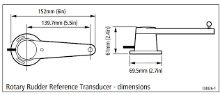
RayMarine Rotary Rudder Transducer – Location
So the first thing we have to do is install the rotary rudder transducer. I’m using an ACU-300, which is going to get interesting. For the Rotary Rudder transducer, I will be using the following parts I purchased:
- Rotary Rudder Reference Transducer – RayMarine
- Tiller Pin
- Ball Joint(s)
- 12″ Stud & Nuts
- Starboard 1/4 thickness
- Starboard 3/4 thickness
- Raymarine ACU-300
Secondly, the one thing that makes this installation rather difficult is that the Sea Star hydraulic steering ram is in a rather awkward location to access. We can access it from the Sole of the rear cabin on the Starboard part of the cabin or underneath the bed. regardless, we will need to get access to the rudder components. The transducer will attach to the Tiller Arm. After about two hours of time trying to determine the where to best mount the RayMarine Rotary Rudder Transducer and related components. I finally decide that its best to install it under the bed. It has the best rearward access.
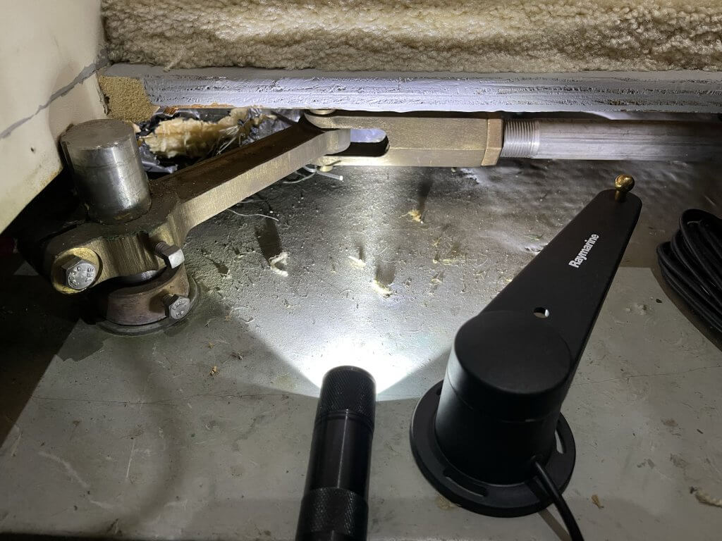
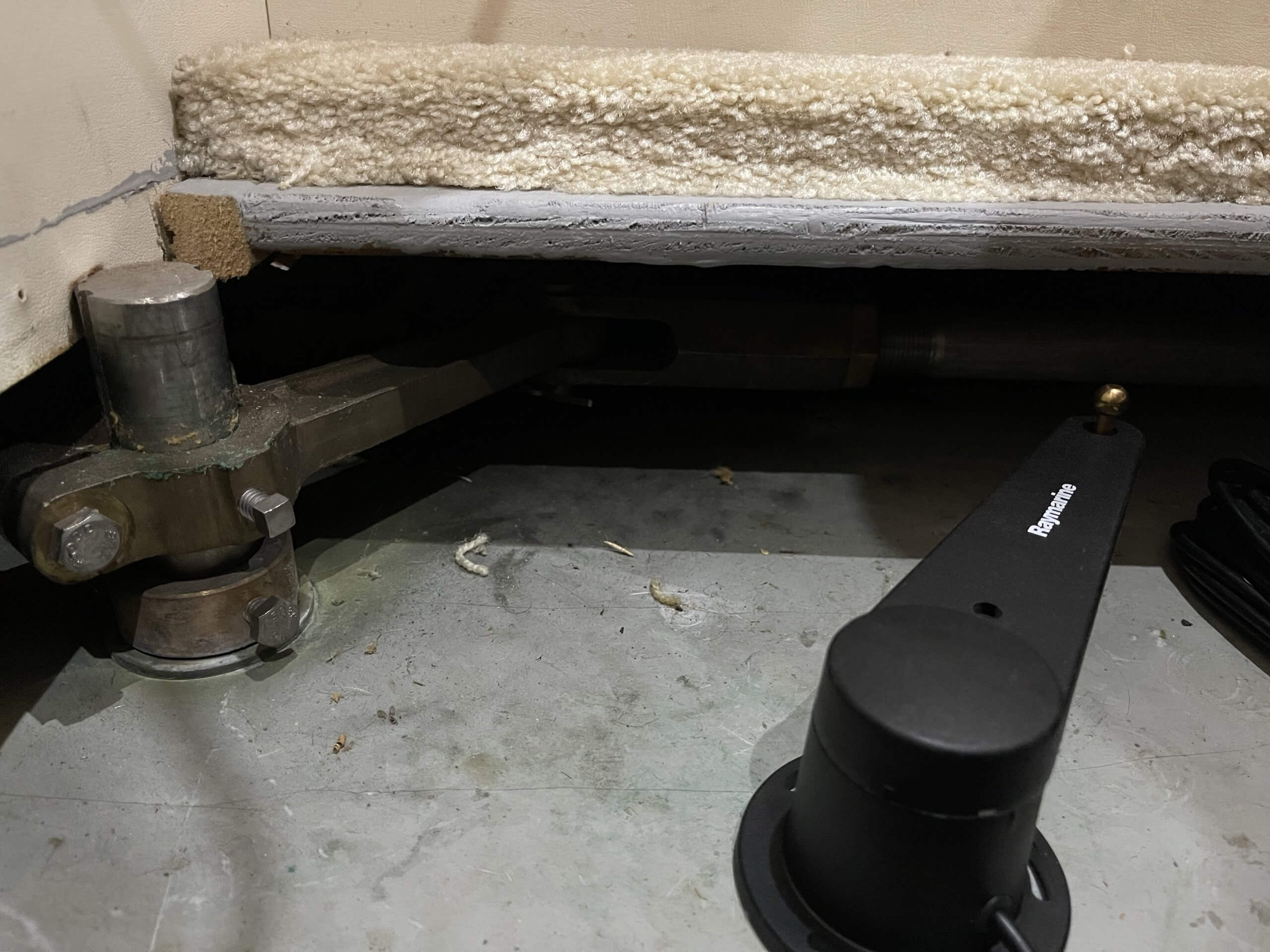
The first location examined was the Starboard Sole of the aft cabin. First you can see the access is rather limited and dark. I’m a small sized person and it was difficult to maneuver around. Secondly, you can see the the Bed access has better access ability to the Rudder Tiller. One thing I’m going to point out is that Rudder Tiller is about six inches in total (End to End). Lastly, this length is going to make things complicated. What with a boat isn’t , right?
Tiller Pin – RayMarine Rotary Rudder Transducer
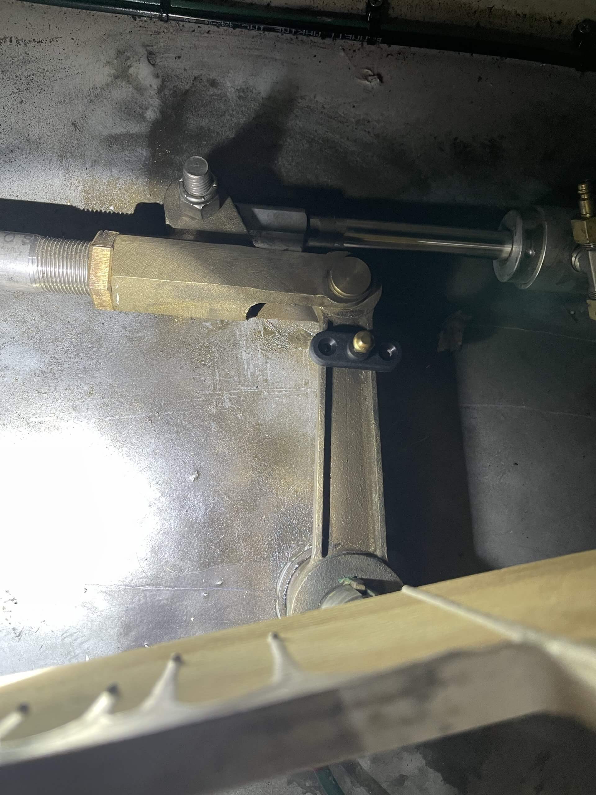
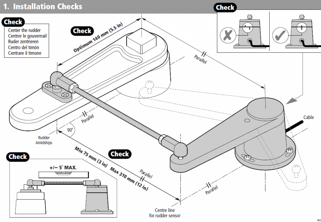
This is the information from the installation manual on how the RayMarine Rotary Rudder Transducer, hardware and how it needs to align. This is an exercise in geometry. Which, I’m not adept at. Everything needs to be parallel & level. I will draw your attention to the suggested length between the tiller pin and the rudder shaft centerline needs to be at 5.5 inches. This is because the Rotary Rudder Transducer itself is 5.5 inches in length too. You can see that the tiller pin wider than the Rudder Tiller arm (Top Right Picture).
Additionally, the 5.5 inches puts it somewhere in the middle of the pin on the steering ram. Secondly, not installing the tiller pin at 5.5 Inches pushes the transducer back by the difference. In my case it will be off by about one inch, which means the Back of the RayMarine Rotary Rudder Transducer will be off from the centerline of the Rudder shaft by that difference.
Tiller Pin Mounting Fabrication – RayMarine Rotary Rudder Transducer
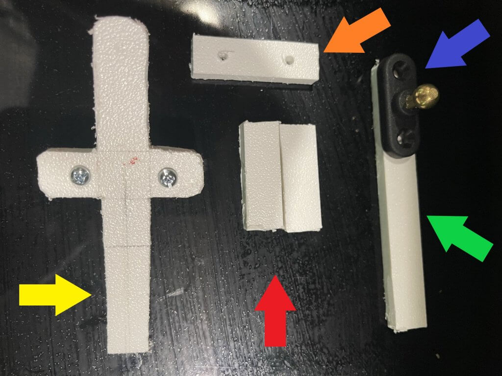
First, I don’t really want to drill into the Tiller Arm. Secondly, I want to get this close to the 5.5 Inches that I can. So I made an extension, Lifting Blocks and Saddle. I feel with these parts I can get this close to the 5.5 inches required. Below you will the custom mounting I’ve created out of 1/4 Starboard. There might not be enough rigidity for this to keep its form. The reasoning behind all of this is to get to the 5.5 Inches. This is so I won’t have to deal with things being off.


As you can see it appears that everything seems to clear and there is no interference. What I will say is I need to shorten the “T” Piece. Further more, I needed to use both blocks (The Smaller Rectangular Pieces Red Arrow). So what this means I will need some longer bolts. Below is a list of the pieces I fabricated and their purpose :
- Tiller Pin Extension (Yellow) – 4.5 Inches (Shorten)
- Bottom Saddle (Orange) – 2 Inches
- Tiller Pin (Blue)
- Tiller Pin Extension Lower (Green) – 4.5 Inches (Shorten)
- Lifting Block(s) (red) – 2 Inches
- Bolts & Nuts – 6-32 x 1.25 Inches (1.5 to 2.5 Inches)
Furthermore, what I will say is they are not perfect in any way shape and form. maybe when my 3d printer arrives in October, I’ll get to making something a bit better. For now I think this will do.
Mock up
Before I do anything I’m going to lay everything out and try to get everything to line up. above is a picture of the layout of how the transducer will mount. I’ve marked the centerline where it needs to line up to the center of the rudder shaft. It’s not going to be perfect. Hopefully, the calibration will compensate for any variance. It should be no further off than 1/16 to 1/4 of an inch on the center line. Like I said, this is all geometry, which I though I would never use in the practical world
Mounting
So with the tiller pin mounted and in place, its now time to place & mount the rotary rudder transducer. In my case, there is a height differential. If you look at the instructions, we can’t be off more than five degrees. So, what I will do is use a 5x4x3/4 pieces of scrap starboard to mount transducer. I may need to add some additional height for the transducer because of the way I mounted the tiller pin. Keep in mind everything has to be parallel and at ninety degrees when the rudder is in the centered position. Lastly, it looks like I’m parallel, and off no more that two degrees. This may be a temporary mounting, until I get my 3d printer.


Rudder Rotary Transducer Mounted & Wired to Fly Bridge
So after a few trails and tribulations I finally got the rotary rudder transducer mounted. It seems to be aligned correctly. You can see in the pictures below that everything appears to be parallel and at ninety degrees as required. I had to add four block to get the correct height. Furthermore, the starboard is not rigid enough so I will fabricate this later in from 1/8 steel stock for the tiller pin mount for the top and bottom saddle. I may even decide to 3d print the entire pin mount.

So if you have a 2000 Silverton 352 you can basically use what I have done as a template. I will say the wiring from the transduce barley reaches the fly bridge. Additionally, the helm console is starting to get rather cramped due to the additional equipment.
Raymarine ACU300 & Rotary Rudder Reference
First, with the Rudder Rotary Transducer installed and the wiring run to the fly bridge, we install and wire the transducer to the ACU300. We required power to the ACU300 and the four wires to the Rudder Reference (Red, Green, Blue, Ground). I created quick connects for the power and the Rudder Transducer.
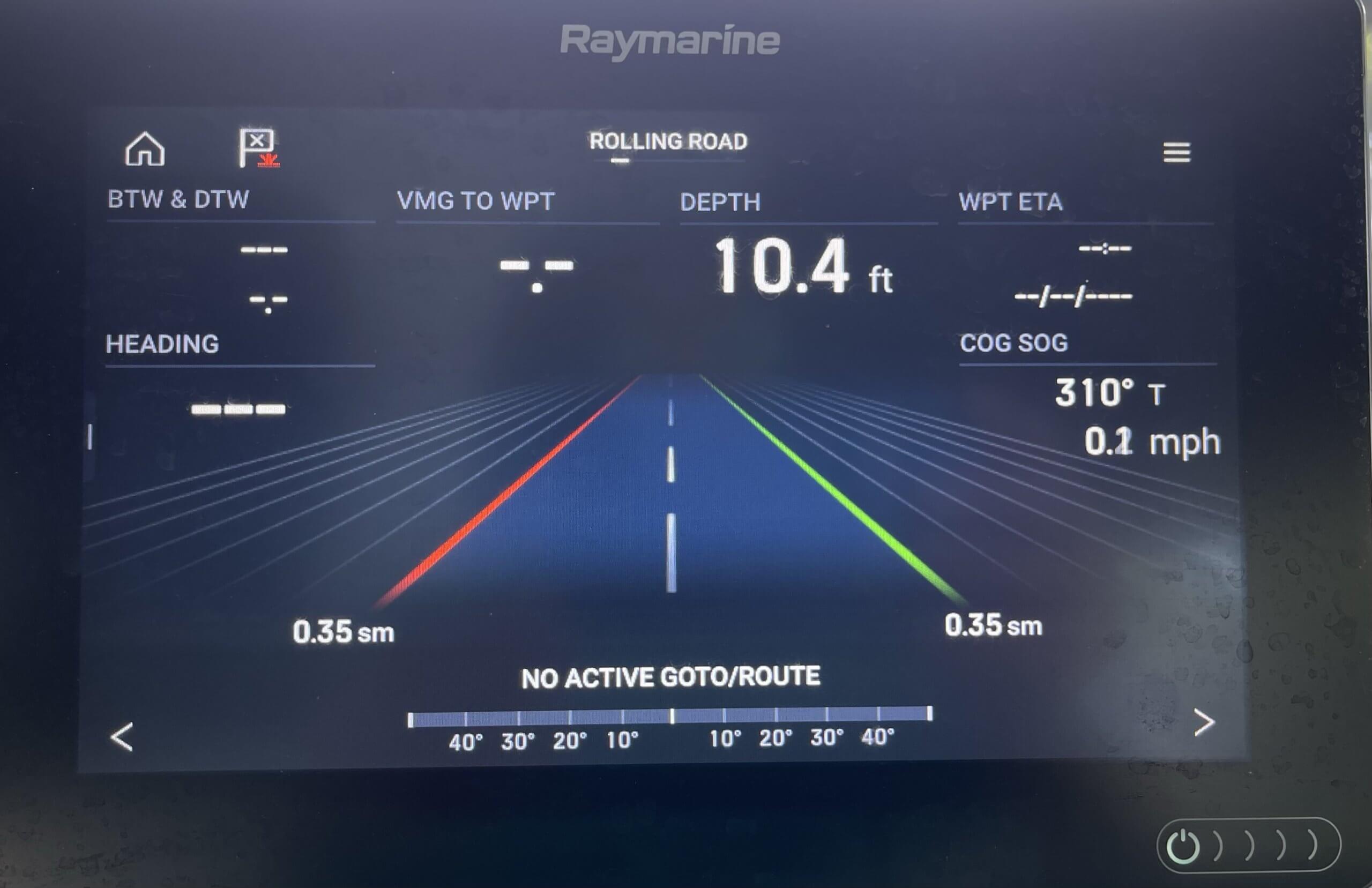
So above you can see that everything appears to function correctly. I have a feeling the alignment mark on the steering wheel is off. Additionally, when the transducer was install the rudder is clearly not aligned to midship / Center. I can not run the Dockside wizard to fix this until I get the Octopus Reversing Pump and EV1 core installed.
Lastly, I will also need to install the RayMarine i70R, into the console. I also want to install the i70’s to replace some of the analog gauges. That will be in another episode, probably with the autopilot pump.
Wrapping things up in this Installment!
So to wrap this up episode up. We have the Rotary Rudder Transducer installed and functioning. The next step is to install the EV1 Core and the Autopilot pump. I would say we are about a third of the way though the Autopilot installation. In the next installment we will install the EV1 Core. Stay tuned and Subscribe to see what we do next.