So we are about nine months into 2023. It’s been almost a year since we initially started working on the autopilot. So we need to complete the RayMarine Rotary Rudder Transducer update. We need to get back to finishing the Autopilot install. We had mocked up a temporary mount, made out of starboard. Furthermore, It accomplished the purpose but was not ideal. Additionally, I have been literally waiting for my Prusa Mks3+ 3D printer for about six months. I changed jobs at the beginning of the year, and I didn’t start back on any of this till May of this year.


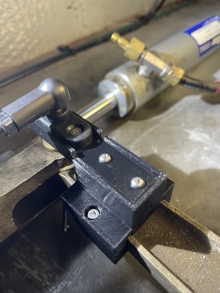
So, we pick up where we left off about nine months ago. We are going to 3D Print the Tiller Pin Mount. Finally, the above picture is the new mounting bracket for the transducer mount pin. I made this out of Prusa Black PTEG. It’s basically three parts.
Table of Contents
Tiller Pin Mounting Fabrication
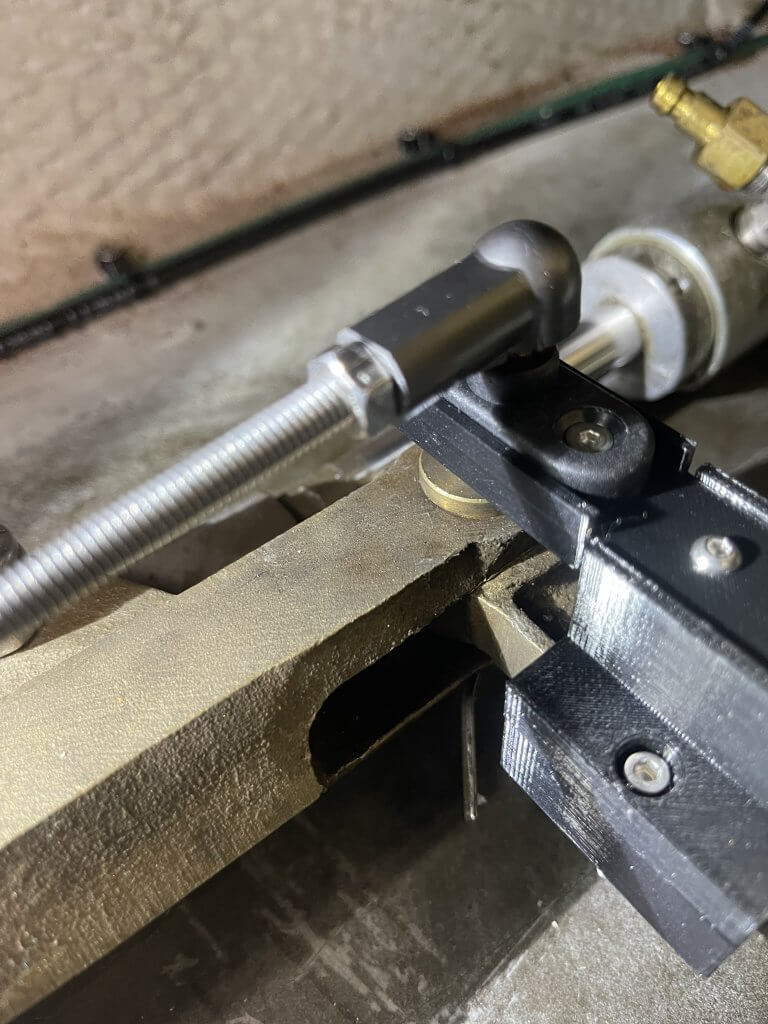
So the first thing we have to do is to re-fabricate the mount. I used a top and bottom clamping mechanism. you can see that in the first picture. below is a list of parts that are needed:
- Rotary Rudder Reference Transducer – RayMarine
- Tiller Pin
- Ball Joint(s)
- 2 – M3 x 30mm hex cap bolt
- 2 – M3 x 15mm hex head bolt
- 2 – M3 x 8mm hex cap bolt
- 6 – M3 hex nuts
- 3D Custom Fabricated Mount
- 3D-printed Bottom Cap
- 3D-printed Top Cap
- 3D-printed pin extension
Below is what the new mount looks like. It took a number of hours to create, revise and re-print. It looks clean and is functional. I did all the modeling in Free CAD and slicing in Prusa Slicer. This is very specific a Silverton 352 MY and it’s tiller pin. Reach out to me if you need one!
Tiller Pin – RayMarine Rotary Rudder Transducer
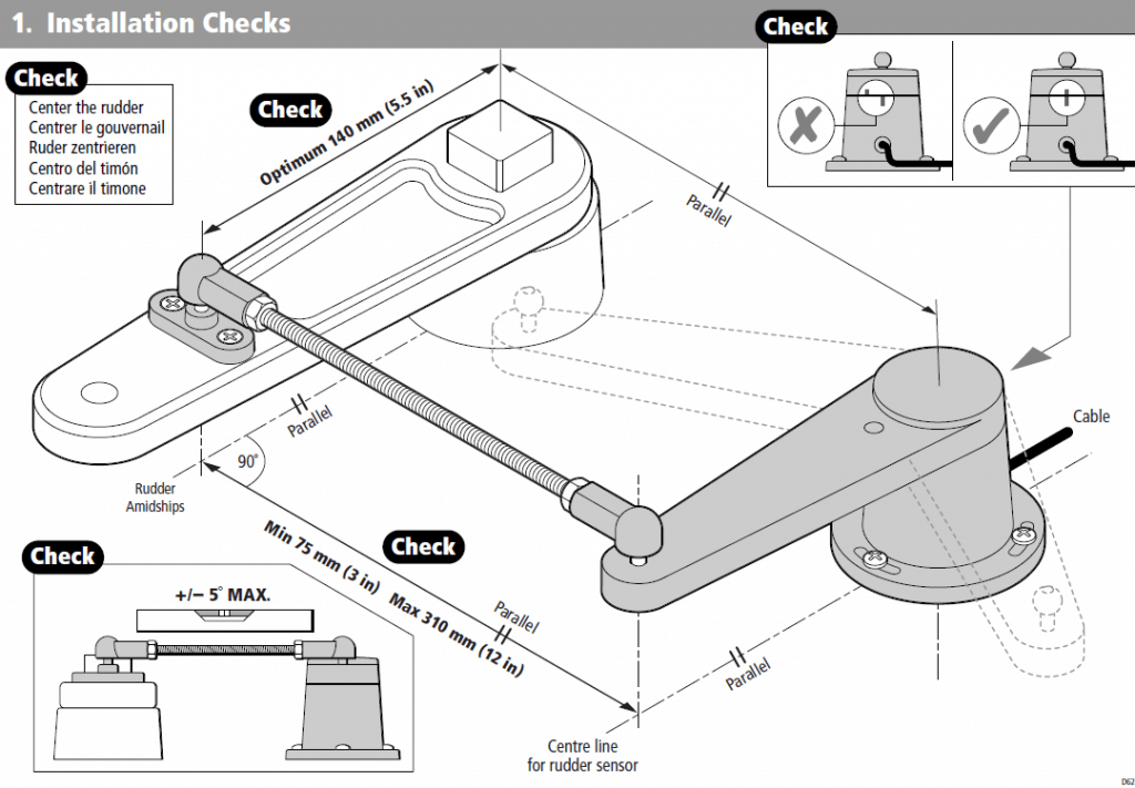
We need to ensure our newly created Tiller mount is correctly designed. This is a review of information from the installation manual on how the RayMarine Rotary Rudder Transducer, hardware, and how it needs to align. This is an exercise in geometry. Which, I’m not adept at. Everything needs to be parallel & level. I will draw your attention to the suggested length between the tiller pin and the rudder shaft centerline needs to be 5.5 inches. This is because the Rotary Rudder Transducer itself is 5.5 inches in length too. You can see that the tiller pin is wider than the Rudder Tiller arm (Top Right Picture).
You might notice that there is a slot in the top mount. This is so that I can adjust the length by .5 inches forward if needed. Additionally, there is a channel for the tiller pin mount. This is to prevent any movement. The 3D printing has led me down an entire rabbit hole of I can make anything I can think of. So be careful, of what time consuming craziness this might unleash.
Additionally, the 5.5 inches put it somewhere in the middle of the pin on the steering ram. Secondly, not installing the tiller pin at 5.5 Inches pushes the transducer back by the difference. In my case, it will be off by about one inch, which means the Back of the RayMarine Rotary Rudder Transducer will be off from the centerline of the Rudder shaft by that difference.
Raymarine ACU300 & Rotary Rudder Reference
First, with the Rudder Rotary Transducer installed and the wiring run to the flybridge, we install and wire the transducer to the ACU300. We required power to the ACU300 and the four wires to the Rudder Reference (Red, Green, Blue, Ground). I created quick connects for the power and the Rudder Transducer.
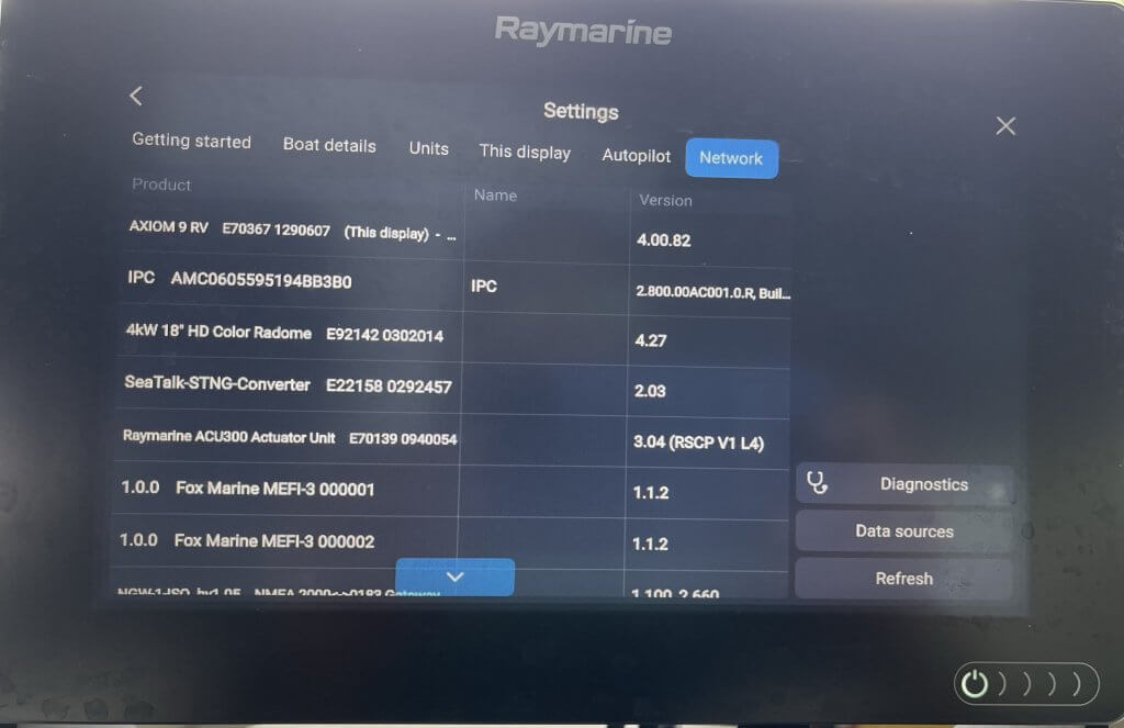
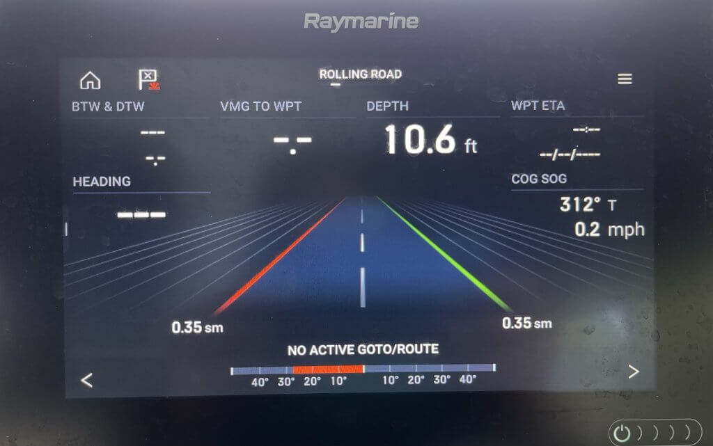
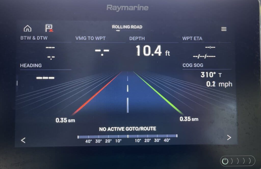
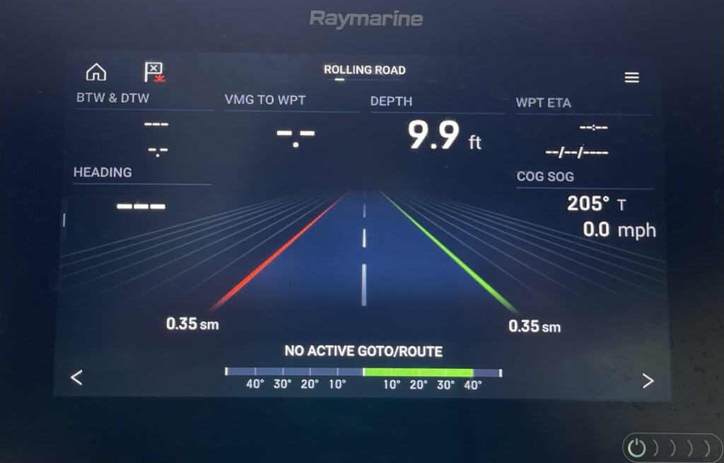
So above you can see that everything appears to function correctly. I can not run the Dockside wizard to fix this until I get the Octopus Reversing Pump and EV1 core installed.
Lastly, I will also need to install the RayMarine i70Rs, into the console. I also want to install the i70’s to replace some of the analog gauges. That will be in another episode, probably with the autopilot pump.
Wrapping things up in this Installment!
So to wrap this up episode up. We have the updated Rotary Rudder Transducer mount and re-installed it and it’s functioning. The next step is to install the EV1 Core, i70Rs and the Autopilot pump. I would say we are about a third of the way through the Autopilot installation. In the next installment, we will install the EV1 Core. Stay tuned and Subscribe to see what we do next.