So in part six, of building the battery monitoring, I said I would add the four additional batteries to monitor. As a result, that led me down the rabbit hole of WiFi Relay switching for controlling devices. You might ask why I ended up here. The reality is I should be able to turn devices as well as lights on and off :
- With a physical switch
- An Application on my phone
- With my voice
- With the SignalK server
So as I poked around with the plugins in SignalK. Additionally, I found an integration for Sonoff. Firstly, I’m very familiar with these devices. I use them with Alexa and Home Assistant. So I was thinking while needing to get the ESP 8266 Voltage Sensor, mounted in a box, why not add a four-channel WiFi Relay Controller to switch some lights on and off via WiFi?
WiFi Realy Switching – The Hardware & Functions
Firstly, you are going to need to purchase the following items to start the assembly of the WiFi Relay Switching.
- Four-Channel WiFi relay module
- A large project Box
- 16 Gauge Wires
- Wireloom
- Two Pin Male & Female water-tight Quick Connectors
- LED Light Bar, 1600LM COB Interior Light Strip w/Switch
- Cable Glands
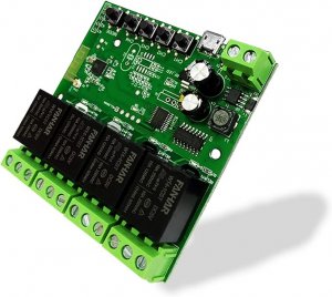
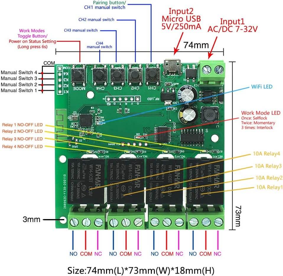
Additionally, above is an example of the board I purchased. More importantly, this will allow us to control four devices. Secondly, in my case, I’m going to add some additional lighting & device control in the bilge. It’s dark down there when I need to work, and this will help. In addition, I sometimes forget to turn off the bilge fan! Furthermore, I can automate this with timers. So, below is what I plan on for the 4-Channel Relay Module
- Generator Room Lights – Alexa/ Signalk/ HomeAssitant
- Engine Room Lights & Rear Shower Sump, AC Condensate – Alexa/ Signalk/ HomeAssitant
- Foreward Shower Sump, AC Condensate & Bilge Pump- Alexa/ Signalk/ HomeAssitant
- Bilge Fan – Alexa/ Signalk/ HomeAssitant
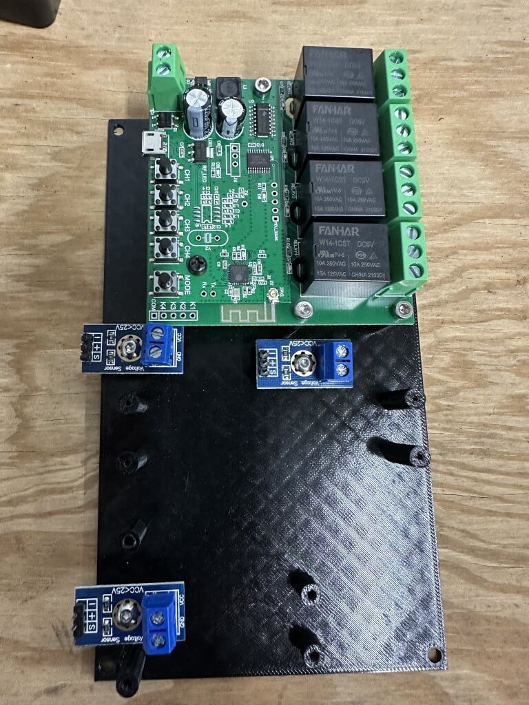
Furthermore, I 3D Printed an insert for the large project box to mount the previous ESP-8266 voltage sensor, the five voltage dividers, and the new four-channel relay module. Additionally, you could just use PCB standoffs and glue them in as I initially did. Lastly, this will tidy things up and secure everything nicely. So, If you need this reach out to me I can send you the STL file.
Wiring, Mounting & Assembly
Firstly, I would strongly suggest you do all the assembly of the WiFi Realy Switching Module and the ESP-8266 voltage sensor ahead of time. Additionally, I would run the external wiring and connectors too. Furthermore, it took me over five hours to rewire and remount everything. So, learn from my mistakes! I had already made everything modular, but the 16 gauge wiring and spacing for the items in the box were not well thought out. Furthermore, below is an example of what the project box for my battery voltage monitoring and four-channel WiFi relay module looks like.
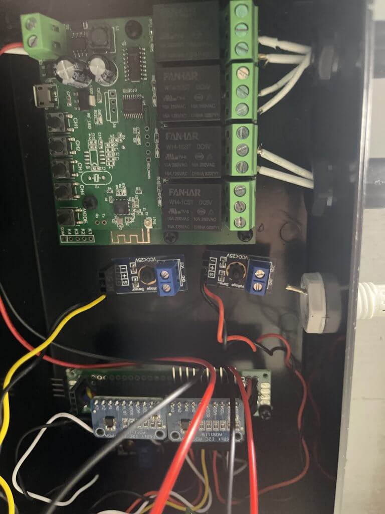
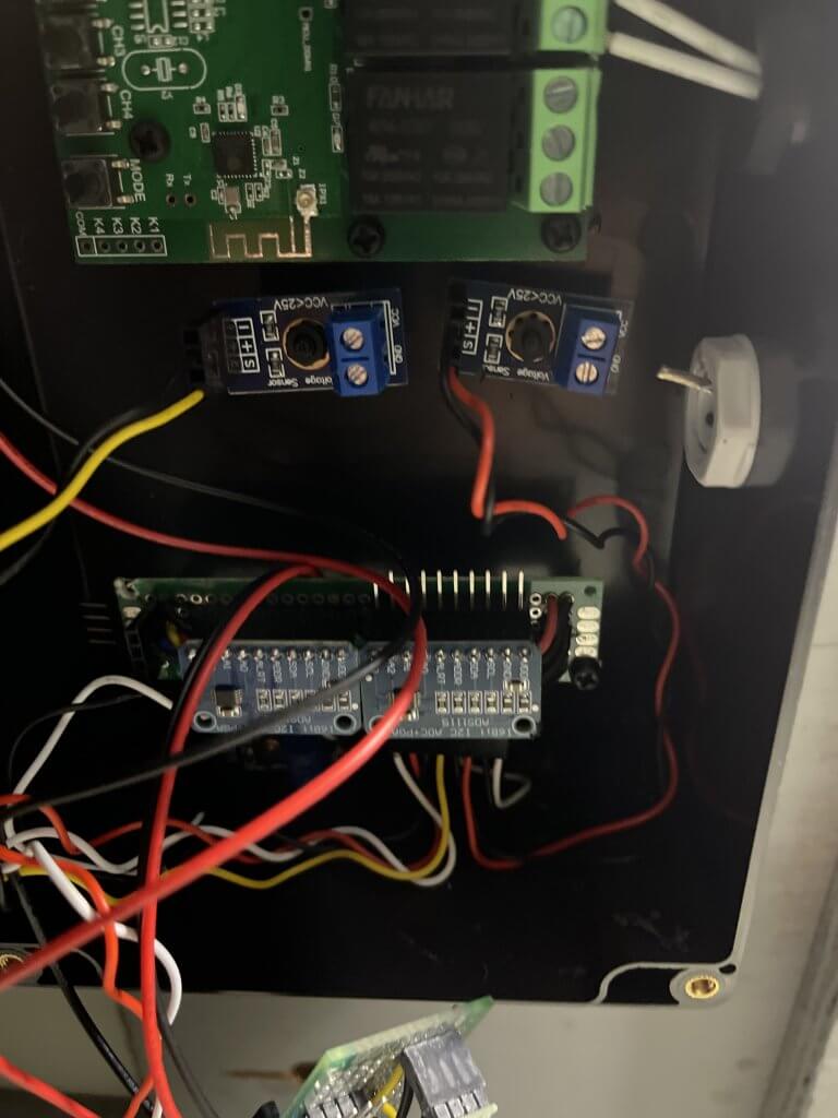 WiFi Relay Switching Mount – View One
Furthermore, keep in mind that this was before I 3D printed the insert for mounting the devices. Regardless, I think you can get an idea of what this looks like. I power both the Four-Channel WiFi relay module and the ESP-8266 Battery Voltage Sensor. Additionally, the power for the modules comes from the generator room battery.
So from top to bottom here is what the relay controls:
- Top Relay – Bilge Fan with timmer setting
- 2nd Relay – Generator Room Light
- 3rd Relay – Engine Room Lights, Shower Sump, Rear AC Condensate
- 4th Relay – Foreward Shower Sump, AC Condensate & Bilge Pump
Firstly, middle picture, about the midpoint of the project box, you can see the Voltage Divider and sensors. These are for the port battery bank. Secondly, below that is the ESP-8266 voltage sensor, and below that will be the starboard battery bank.
Lessons Learned
There is a lot crammed into the project box. Furthermore, I would really look into laying this out ahead of time instead of doing what I did. Lastly, the first picture shows you the 3D mount I made for the devices in the project box. I’m now using a Bambu Carbon X1 to print parts.
Wrapping things up in this Installment!
So to wrap this up episode up. We have updated the components for the ESP-8266 Voltage monitoring device and added a four-channel WiFi switch. The next step is to add the two additional starboard batteries to the monitor. I would say we are about half of the way through the installation. In the next installment, we will install the revised code on the ESP-8266 via Over The Air – OTA. Stay tuned and Subscribe to see what we do next.