So there is an error for out MerCruiser Alpha One Gen II and the Trim position Indicator. It’s a 130 Error at startup on our 2007 Sea Ray 210 Select. Additionally, there are some posts that say I can replace these without removing the outdrive. So do I want to deal with the hassle of maneuvering around the gimble to remove and install the bolt that holds the plug for the limit and position sensors? So will I attempt to take the outdrive off of the gimble. It looks Simple enough going through the service manual? Famous last words right? So maybe we will start the removal of the MerCruiser Alpha One Gen II outdrive so we can replace the Alpha One Gen II Trim Sensors trim sender and limit switches.
The MerCruiser Alpha One Gen II Trim Sensors Replacement steps
To start the Alpha One Gen II Trim Sensors replacement move the outdrive into the lowest position. Turn The outdrive to starboard and remove the port trim limit switch. Next, turn the outdrive to port and remove the trim sender switch. Tape these out of the way and move the outdrive port. I will now attempt to remove the sender wire retaining bolt.
Trim Sensors Retaining Plug retainer (Removal)
So I was able to remove the bolt and plug retaining ring that holds the Alpha One Gen II Trim Sensors limit and sender units using a wobble extension. I remove the Trim Limit and Sender wires after disconnecting them on the inside of the hull. I’m just removing the bolt here, and that was difficult enough
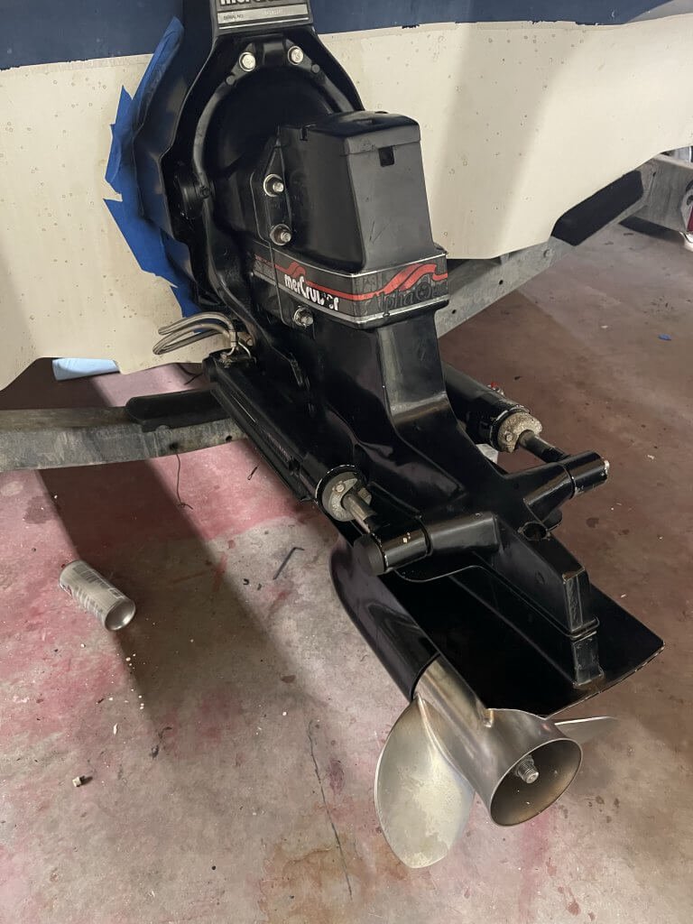
MerCruiser Alpha One Gen II Outdrive (Removal)
First, we start by putting the transmission in forward gear. I didn’t do this so I will probably face the consequences later when trying to re-assemble. Secondly, after you put it in forward, remove the trim switches which I already have done. Next, you put the outdrive in the furthest up position. You then remove the speedometer fitting. Mine is missing. Thirdly, move the outdrive to the furthest down position. Then remove the six bolts, rear hydraulic clips / pins and remove the outdrive. It was very difficult getting off. Probably a result of me not putting it in the forward position. Next, remove the two hinge pins. These are in with about one hunderd foot pounds, so they are hard to remove. up to this point we have the outdrive of the MerCruiser Alpha One Gen 2 and sensors removed. Now the fun will start!
MerCruiser Alpha One Gen II (Issues)
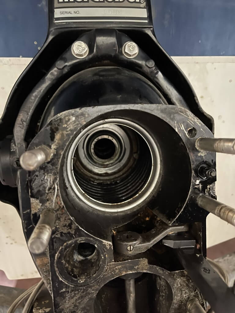
So, what I find here is just like most of the work that has been done to the boat. It’s a mess at the best with no indication of how or why it was put together like this? What I can tell here is water in the upper bellow. The gimbal bearing looks new. The bellows also look new, so why is there water in here? Additionally, there appears to be leftover gasket material on the left side. I kinda scratched up some of the Mating surfaces getting it off, maybe? You can see that in the picture below. More rust is all I can say! I’m starting to sound like a broken record!
The removal of the bell housing gets me just a little more room to maneuver around, but not enough. So I head off to Amazon and order a few parts that are needed. I will need the room to fix the trim sender and limit switches. I also need a tool to remove and install the silver retaining ring that holds the bellow to the bell housing. I’m going to try and reuse the ring.
Remove the main U Joint bellow and retaining ring
So following the procedure in the manual loosely. I’m going to remove the retaining ring that holds the bellow to the bell housing. There is a specific tool that is used to accomplish this. I bought it to be sure I can do this without damaging the ring. First, You slide it in and then using my makeshift pulling mechanism using a six-inch bolt, nuts, and washers. It won’t take much to remove the ring.
So once you have the retaining ring removed twist the bellow ninety degrees, this will give you enough room to get access to the bolt if you need to remove it or install it. It’s still pretty tight. I was still having a difficult time getting the retaining clip and bolt installed. So while I was picking up parts at the store I picked up a different bolt.
How do I these back in and What wire pairs go to where?
I previously removed the bolt, plug retaining ring, and sender and limit switches, secondly I run one trim limit switch wires in through the same hole and pull it into the boat. I do have a lot of room in the boat so I don’t have to use a pull string as I have seen others do. But what I will do is pull the trim sender with the trim limit switch. I taped the trim sender to the limit switch wire which I had enough length to pull. Additionally, you really can’t get these wire pairs switched around in my case. The trim limit switch is two male bullet ends and the trim position sensor is a male and female bullet connector. Regardless I labeled the trim limit switch with tape so I know which was which.
The more difficult part, to say the least!
Now, the more difficult part is trying to get the bolt and the plug retaining clip back in. Secondly, I’ve tried multiple times to get this back to no avail. This was very frustrating. The new half plug ends are not attached like the old ones. So I’ll silicone them and see if that helps the situation. Lastly, the bellow retaining removal and install tools came in. Additionally, I will need a length of flat stock and threaded rod, washers, and bolts. Off to Lowe’s I go!
Additionally, I replaced the four-point bolt with a Stainless Steel Hex Head Socket Bolt. It was too difficult to maneuver on the head of the socket The bolt that holds the retaining clip is a quarter-inch by 3/4 length, 20 pitch bolt. I could not find one other than an inch length so I cut it down. Not perfect, but a Dremel with a cut-off wheel and a file assisted in the process. This makes the installation of the plug retainer ring simpler. It should be easier if I ever have to do this again. I hope not.
Re-Install the main U Joint bellow and retaining ring
The next part of the process is to re-Install the main U joint bellow. Rotate the bell housing ninety degrees back to its original position. I manhandled the bell housing and so the bellow came out of the indentation that is in the Bell housing. I put the hinge pins and hand tighten them. You will need to Locktite these, I did. Next, I pull the lip of the bellow into the indent and then insert the retaining ring. I place it and set it into place using the install tool and a dead blow hammer. Don’t go crazy here, it’s just a retaining ring.
Now it gets super frustrating putting the outdrive back on!
A couple of important lessons to be learned here. So put the rubber gasket in the right place on the inside of the bell housing in front of the bellow retaining ring. It’s gets glued in there and adhesive goes on the snout of MerCruiser alpha one gen II outdrive. I decided to wing it and I tore up a gasket in the process and wasted an hour of my time.
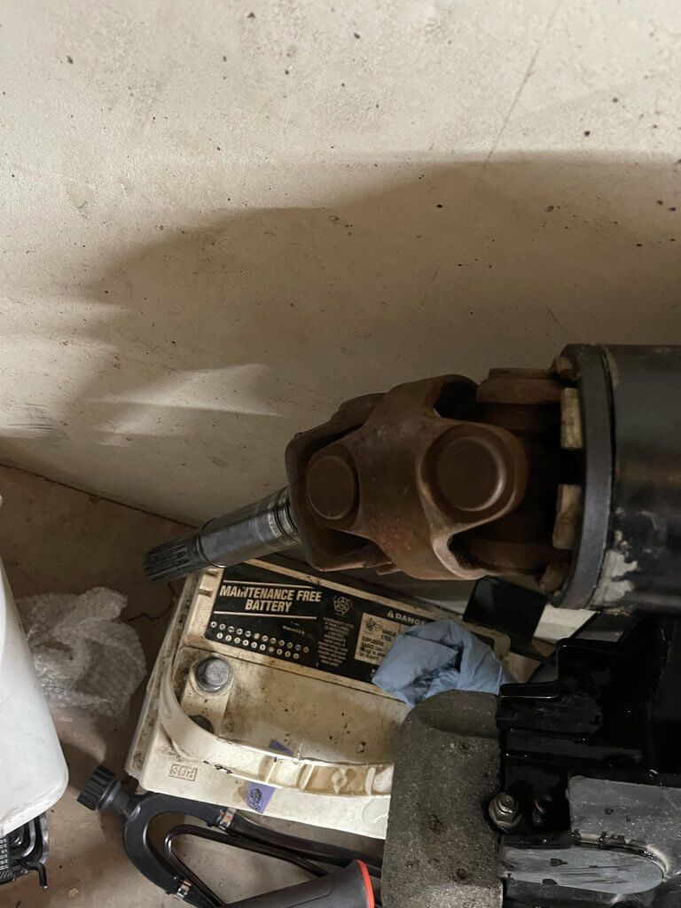
To get the out drive shaft in you need to make sure it aligns correctly with the splines. It may take Turing the prop shaft to get this to happen. Also, be aware the gear shift has to be in forward and it must align correctly to the fork on the shift mechanism. Additionally, make sure it goes together easily, with no forcing to get this to go back together. So try to refrain from using a tool to get it on. Be aware, there is an o-ring on the Tighten the six hex head bolts, to the recommended torque values.
Put the Trim Limit and Trim Sender switches back on to the housing
So I put the Trim Limit and Trim Sender switched back on. I still have to address the broken Trim Limit bolt. I will have to drill this out and possibly Helicoil it. With that all done, we need to set the limit and senders to the base initial setting. Follow the manual. It’s pretty simple, but I have a feeling it going to be like everything else, I think it’s simple and it turns out differently. It’s just the way things seem to go.
Now that at out drive is back on!
So with the out drive back on, it’s time to connect and adjust the sensors. First, I connect everything as it was. This is a non DTS boat. That one statement is going to be key. So following the manual, I set the port sender as indicated and make whatever adjustments he doing to mitigate the 130 error. There is a procedure for setting of the gauge. I no longer have the sea ray specific four in one gauge. I have the new SC1000.
Alpha One Gen II Trim Sensors – Adjusting the trim indicator
These two switches starting with the trim indicator are going to be a time consuming process. There will be a lot here that is not in the manual. So after is adjust the indicator to what I think is the zero position in the manual. It’s time to set the baseline on the gauge for full down, trailer and maximum up limit when under power.
So I do that and I notice nothing is changing on the gauge. It’s still gives me a error. So off to the electrical diagram for the boat and to check the wiring. This is where the first part of the fun begins. The wiring diagram seems to indicate that this goes back to the ECU. So do I have the right trim indicator?