So it’s a new year 2022 with new opportunities. We are making our way through modernizing “The Nauti Oar”. We are making our boat an IoT or connected boat. What is next in our series is to build a sensor and get it sending data to the SignalK server. How we do this will be by using our setup of SignalK and building an Arduino Fuel Level Sensor. Where are going to start is with a Port / Starboard Fuel tank sensor. Additionally, I will add a battery voltage as an input to the Sensor.
Really part five, now the fun begins!
So, now we are at the critical event of our Modernization. To recap, in the fourth part of this series. We finished the installation of the Raspberry Pi 4 and the SignalK Server and plugins. What we will do next is build a Sensor. This will be a WiFi Fuel Tank Level and Battery Voltage Sensor. What I will need is the following Hardware:
- ESP-12F Node MCU
- ADS 1115 – (16 Bit Four Port Analog to Digital Converter)
- Buck Converter Board 3A
- Voltage Detection Module DC 0~25V
- Female to female 4P Dupont jumper wire
- Adjustable Power Supply or USB Power
- Fine Tip Soldering Iron
- Solder Prototype Boards
- Solder and Colored Wiring (24 Gauge)
- Bread Board Kit & Jumpers
I was able to find most of this stuff on Amazon. There is a fair amount of skills that are necessary to build these sensors. It’s been at least thirty years since I’ve breadboarded or Prototyped anything this complex. I had to do a bit of this to fix the captain’s call on “Piperealla”. Additionally, You will need to have an understanding of basic electronics and circuits. Lastly, there is some programming software that you will need but we will get to that later after we breadboard the sensor. So let’s get to building our first sensor?
Arduino Fuel Level Sensor Build – Breadboard
Let’s start by breadboarding the sensor. This will allow us to quickly prototype and troubleshoot any issues that may arise wiring-wise. The breadboard is basically a big pinned electrical strip. We use jumper wires to accomplish this. These jumpers allow us to create a circuit. Keep in mind we can power the device by the USB port or external power. In my case, I will use a buck converter to accomplish this. When I program the ESP8266 for the first time, I will use the USB port to accomplish this. I pull it off the breadboard to do this.
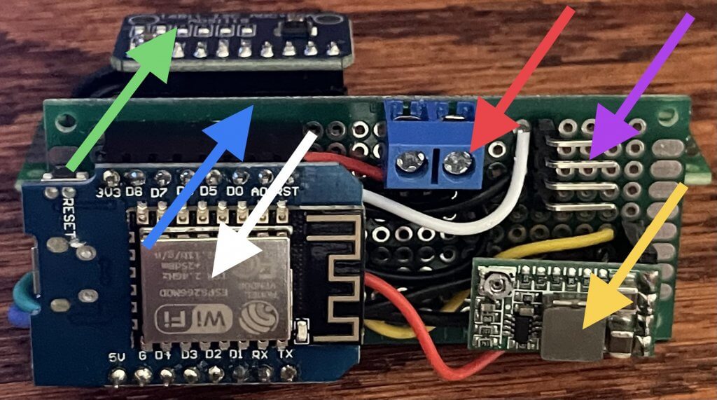
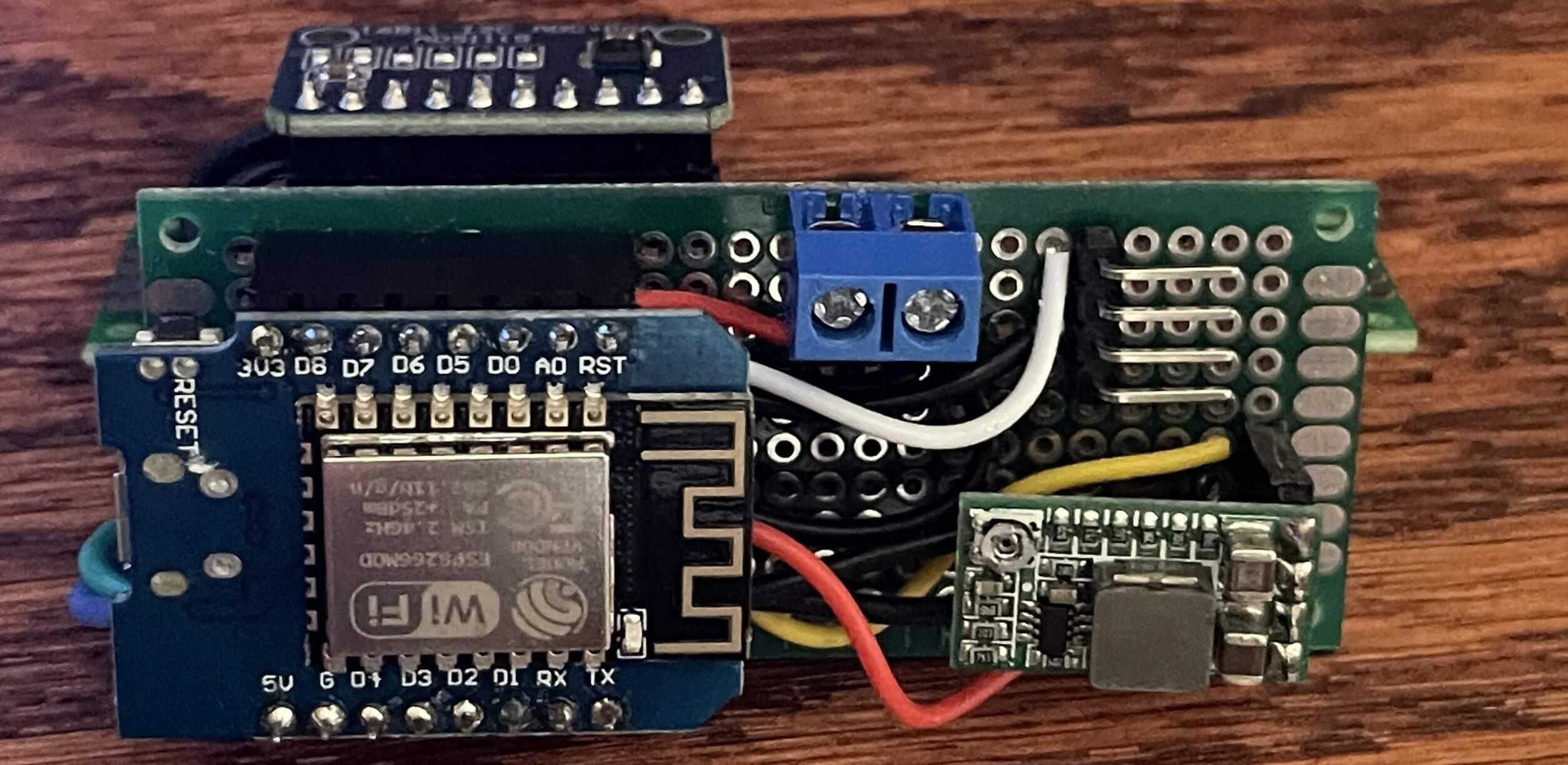
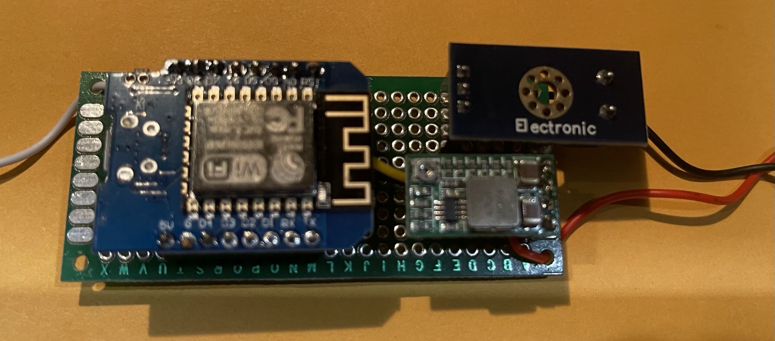
In the picture above you can see where I will eventually end up. I made this prototype sensor based on a modular design. More importantly, I can swap out devices if they fail easily. Additionally, It gets quite difficult at times soldering these devices. I’ll point out what the devices are that are denoted by the colored arrows:
- White Arrow – ESP-12F Node MCU (Arduino)
- Red Arrow – Power Input (0-24V)
- Yellow Arrow – Buck Converter Board (3.3V)
- Purple Arrow – Four Pin A0 analog input Native 10 Bit A to D Converter
- Blue Arrow – Ten Pin Female Pin to ADS1115
- Green Arrow – ADS 1115 External I2C for port 16 Bit A to D Converter
So the sensor pictured above is where I will end up eventually after Breadboarding. This is a bunch of wiring and Soldering. I’m not doing this for volume so one-off customs will do.
Arduino Fuel Level Sensor Build – ESP8266 / ESP-12F Node MCU Pinning
Firstly, we are going to start by assembling/Pinning the ESP8266 by adding the header pins. We need to Solder the header pins to the ESP8266. In my case, I used a male and female header on the ESP8266 on my prototype board. I keyed the ESP so I can’t orient it incorrectly. If you are not concerned about that just use the short end of the eight-pin male headers that came with the ESP8266 kit. For breadboarding just use the male pins. The Female pins will not extend into the breadboard.
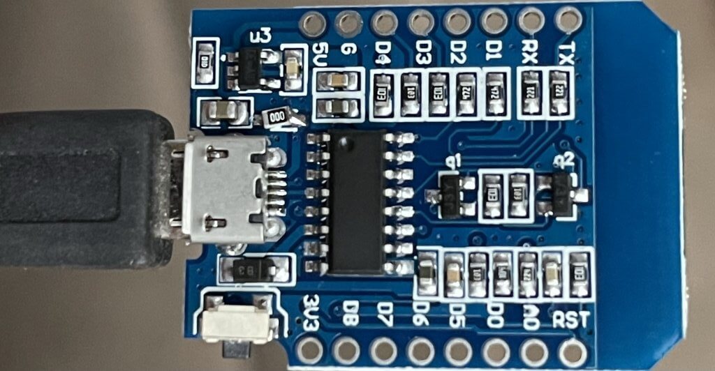
So, to start, there are two rows of eight pins. Above is a Picture of the ESP8266 before I soldered it. Additionally, it can be tricky to get this soldered, especially with the keyed approach (Male & Female). For the keyed approach, use the male and female to keep the ESP8266 level while soldering. For the male pinning just put them in the breadboard and solder them. I use a fine tip and adjustable soldering iron in my soldering station. You don’t need all that, I just happen to have that device for my Sea-Doo digital instrument repair.
Once you have the ESP-12F/ESP 8266 header pins soldered, it’s time to move on to Pinning the ADS 1115. So, basically, it’s the same process. Just a bit more difficult because there is just one row of pins.
Arduino Fuel Level Sensor Build – ADS 1115 Pinning
So as with the ESP-12F/ESP 8266, you will need to solder the header pins to the ADS 1115 board. This will be the short end of the ten-pin male header pin. This will be tricky likewise, but I’ll try and explain how I accomplish this. solder just one of the pins on one end or the other of the ADS 1115. Additionally, you just need to get one pin though. Then heat it back up and get the correct alignment by using the other side of the header where there won’t be hot.
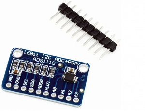
First, keep in mind that the ADS 1115 uses the I2C bus/ Protocol. You can have quite a few I2C devices. Each device has its unique address and must be set on the devices if there are multiple devices like the ADS 1115. In my case, I will have two.
Once you have the ADS 1115 header pins soldered, it’s time to move on to Pinning and configuring buck converter. This is how we will provide power to our ESP-12F Node MCU and a related devices.
Arduino Fuel Level Sensor Build – Buck Converter Pinning & Configuration
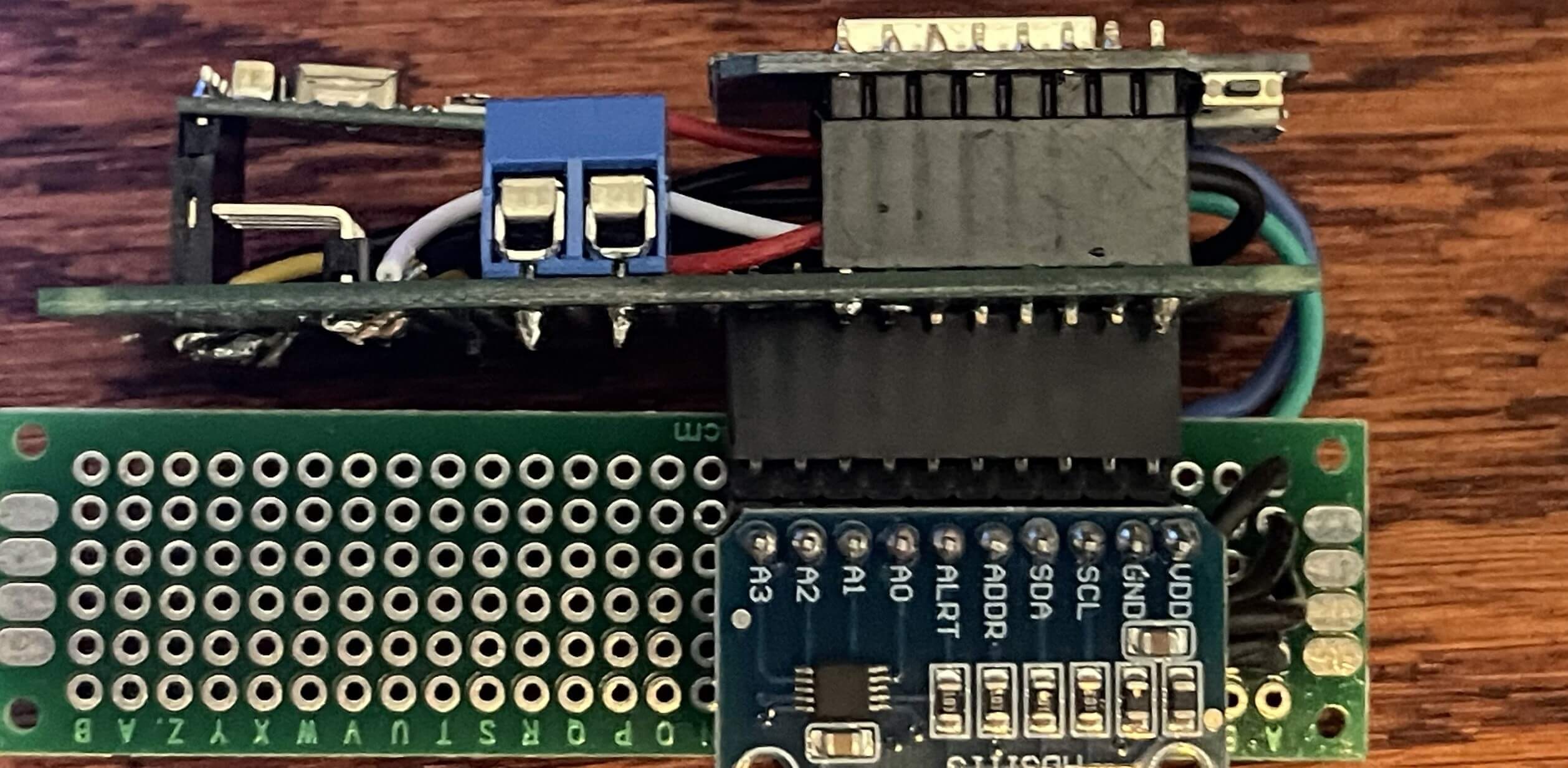
So the buck converter is either adjustable or hardwired to the desired output voltage. We are going to hardwire it! The ESP-12F/ESP 8266 can accept either 5V or 3.3V. Anything above ten percent will burn up the ESP-12F/ESP 8266. Done this once because of a bad connection on the buck converter. Rendering it useless. We are going to go with 3.3V.
Below are the two changes to the buck converter that are needed to set this to 3.3V. First, the red arrow is where you will cut the trace. It’s labeled ADJ. This sets it to a fixed voltage.
Secondly, the yellow arrow is where you will solder the two pads to create a bridge. This one is labeled 3.3V. After that is done solder the short end four-pin male header. Additionally, below you can see all three devices installed into the breadboard. This is not the final layout, but you get the general idea of the layout.


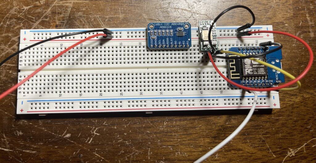
Breadboard Jumper Wiring – Arduino Fuel Level Sensor Build
So, with all the Pinning/soldering complete, it’s time to start connecting our jumper wires to wire up our devices.
Buck Converter Wiring
I will start with the Buck Converter. It has four pins but only three are used. So, snap it into the breadboard. In my particular scenario, I’m powering the ESP-12F/ESP 8266 with an adjustable power supply set at ~12 Volts. I will connect the following pins and jumpers as such for the Buck Converter:
- VDD – This is the 3.3V output to the ESP-12F (Yellow Jumper)
- Pin 49h
- GND – This the Ground from the Power Supply (Black Jumpers)
- Pin 48h
- Rail (-)
- IN+ – This is the Positive output from the Power Supply (Red Jumpers)
- Pin 47h
- Rail (+)
- EN – This is not connected
- Pin 46h
Keep in mind that all the grounds are shared. Be keenly aware of inputs and voltage minimum and maximum values. Additionally, the onboard 10 bit A to D converter on this device (ESP-12F Node MCU) has a built-in voltage divider circuit. So, it can take upwards of 3.3 volts. The translation means 0 volts is zero and 3.3 volts is 1023. We are going to be using the onboard A to D converter to measure the battery voltage of one of the battery banks. Additionally, I will use an external voltage detection module to get the 12V into the required range. I will use the ADS 1115 to measure the Fuel Tank Levels as well as the Water Tanks. I need the additional resolution of the ADS to do get the correct ratios.
The ADS 1115 A to D Converter has the ability to four single inputs or two differential inputs. In the case of the fuel gauge I have on the bench for testing from a sea doo. It has a full value of ~5 ohms and a empty value of ~90 ohms. I’m using a 12V as the input voltage to the circuit. In my case the resolution is very small and does not change the value on the analog input much maybe one to four units in variation. I think the fuel tank on the boat resistance range is ~30 ohms empty and 300 ohms full.
ESP-12F and Buck Converter Wiring
Once you have got the buck converter wired up/Jumpered, we will move on to the ESP-12F. So, snap it into the breadboard. Secondly, I have it hanging off the end in case I have to use the USB port. I will connect the following pins and jumpers as such for the Buck Converter and the ESP-12F:
- 3V3 – This is the COMMON 3.3V Output from the buck converter
- ESP-12F and the Buck Converter (Yellow Jumper)
- Pin 61a to Pin 49h
- GND – This the COMMON Ground from the buck converter
- ESP-12F and the Buck Converter (Black Jumper)
- Pin 61j to Pin 48h
- A0 – This is the + analog input from the 10 Bit ESP-12F A to D Converter
- Voltage Divder / Voltage Detection Module (White)
- Pin 54a
With that all done we should be at a point where we can power up the ESP-12F and see if we can see the device broadcasting its SSID on the WiFi Network. There is no configuration on the device at this point. If all is good you should see the device and be able to connect it. It will show up on the network as SSID (FaryLink_x1xExD). so, if you don’t see it there is a problem with the wiring or the device itself. We need the device wired correctly to proceed. In our next step, I will load the software to configure the sensor in the next step.
Programming Dependencies – Arduino Fuel Level Sensor / Voltage Sensor
Firstly, I will need to download install some software to configure the Sensor. Keep in mind I’m using a windows 10 laptop. So, in my case, I will pull the ESP-12F Node MCU off the breadboard and program it via the USB port. Secondly, to preform the programming of the ESP-12F Node MCU. You will need the following pieces of software:
- Microsoft Visual Studio Code (Winndows / Mac / Linux)
- Platform IO Plugin (Winndows / Mac / Linux)
- Windows GIT (Windows)
- Arduino IDE (Optional)
So to start, first, download and install Visual Studio Code. Second, once you have “Microsoft Visual Studio” installed you will then add the “Platform IO Plugin”. Next, select “Extensions” from the left toolbar. Search for “platformio”, select the first result, and click “Install”.Thirdly, install “Windows GIT”. Additionally, I installed the “Arduino IDE”. There are some nuances that “Microsoft Visual Studio” and “Platform IO Plugin” are not so easy to deal with that the “Arduino IDE” Handle like clearing the flash. Additionally, there are a lot more programming examples for Arduino vs SensESP. I’m not all that savvy at coding or programming.
Programming – Arduino Voltage Sensor
Once you have PlatformIO installed, its home screen should open automatically when you start VSCode. On the PIO Home, select “New Project”. Enter a name (something like SensESP_Test for your first project) and then select “NodeMCU 1.0 (ESP-12E)” in the board dropdown. (This assumes you’re using a Node MCU ESP-12E/F based development board. If you’re using a different ESP, select that in the board dropdown.) The Arduino framework should become automatically selected. Complete the New Project dialog, then open the project you created.
Platform.ini
Once you have your new project open, open the automatically generated platformio.ini file that’s in your project’s directory (NOT the one that you find if you go down into the .pio/libdeps/… folders). Save it as platformio.ini.auto so you can refer back to it.
Create a new file, and copy/paste the entire contents of this example platformio.ini file into it. Save it as platformio.ini.
If the [platformio] section of this file contains your ESP board, make sure your board is not commented out, and that all other boards are commented out, and save it. This should be a good platformio.ini file for SensESP. If your board is NOT included, you need to add it (see how it’s represented in the platformio.ini.auto that you saved). And you need to merge the other lines in platformio.ini.auto into your platformio.ini file. (Detailed instructions for merging these two files are available in the Wiki.)
[platformio]
;set default_envs to whichever board(s) you use. Build/Run/etc processes those envs
default_envs =
   ;esp32dev
   d1_mini
;   esp-wrover-kit
So the Node MCU ESP-12F is actually a d1_mini. So we are good to go from a platfrom.ini perspective.
Main.cpp
Now, open src/main.cpp. The default template is for the Arduino IDE, but a SensESP main.cpp file will look very different. Replace the contents of main.cpp with the contents of one of the SensESP examples in the examples subdirectory here on GitHub. (This is a good one to start with: https://github.com/SignalK/SensESP/blob/master/examples/analog_input.cpp .) Below is an example of what works for me. This will read the analog pin A0. Additionally, Do not apply voltage to the input pin at this time. We will address that in the next part of our series.
// Read Analog A0 Voltage

#include <Arduino.h>


#include "sensesp_app.h"
#define USE_LIB_WEBSOCKET true
#include "signalk/signalk_output.h"
#include "transforms/linear.h"
#include "sensors/analog_input.h"
#include "transforms/voltage_multiplier.h"


// SensESP builds upon the ReactESP framework. Every ReactESP application
// defines an "app" object vs defining a "main()" method.
ReactESP app([]() {

// Some initialization boilerplate when in debug mode...
#ifndef SERIAL_DEBUG_DISABLED
  SetupSerialDebug(115200);
#endif

// Create the global SensESPApp() object.

// Create the global SensESPApp() object.
  sensesp_app = new SensESPApp("Port_Sensor", "wifi_network_name",
                               "wifi_pssword", "Signalk_server_name_or IP", 80);

// The "Signal K path" identifies this sensor to the Signal K server. Leaving
// this blank would indicate this particular sensor (or transform) does not
// broadcast Signal K data.
// To find valid Signal K Paths that fits your need you look at this link:
// https://signalk.org/specification/1.4.0/doc/vesselsBranch.html

const char* sk_path = "electrical.batteries.1.12V.voltage";

uint8_t pin = A0;
int read_delay = 500;
   const char* analog_in_config_path = "/batteries_1_voltage/analog_in";
    const char* linear_config_path = "/batteries_1_voltage/linear";
const float multiplier =0;
const float offset = 0;

auto* analog_input = new AnalogInput(pin, read_delay, analog_in_config_path);


// Wire up the output of the analog input to the Linear transform,
// and then output the results to the Signal K server. As part of
// that output, send some metadata to indicate that the "units"
// of the value we are sending is a "ratio" - which is the official
// unit type for a percentage represented as a float between 0.0 and 1.0
// See https://github.com/SignalK/specification/blob/master/schemas/definitions.json#L87
// for more details.
analog_input->connect_to(new Linear(multiplier, offset, linear_config_path))
      ->connect_to(new SKOutputNumber(sk_path, "", new SKMetadata("V")));

  // Start the SensESP application running
  sensesp_app->enable();
});
Check that the settings (pin numbers, etc.) match your hardware. Then click on the checkmark icon on the blue status bar along the bottom of your screen. (That’s the “Build” shortcut.) If the build succeeds, you can plug in your ESP board and press “Upload and Monitor”.Hopefully, the project compiles and uploads, your ESP will be running the example code. (If you get errors about missing libraries, look at this Troubleshooting guide in the Wiki).
Since the first thing it needs to do is connect to a Wi-Fi network, and it doesn’t know what network to connect to, it will broadcast a Wi-Fi SSID for you to connect to so you can configure it. Connect your computer or phone Wi-Fi to the “Configure SensESP” network. A captive portal may pop up, but if it doesn’t, open a browser and go to 192.168.4.1. Enter your Wi-Fi credentials to allow the device to access the network that your Signal K Server is on. Also enter a suitable name for the ESP, for example, Port_Sensors. (No more than 16 characters, no spaces.) Save the configuration with the button on the bottom of the page, and the ESP will restart and try to connect to your Wi-Fi network.
Connecting the Sensor to the SignalK Server – Arduino Voltage Level Sensor
Once on the network, SensESP should automatically find your Signal K server, assuming it has mDNS enabled (see instructions below). So, first, bring up the SingnalK Server web page (http://localhost or http://remoteip). Next, login as Admin into the Dashboard via a web browser, select Server – Settings from the left side menu and make sure the “mdns” option is ON.
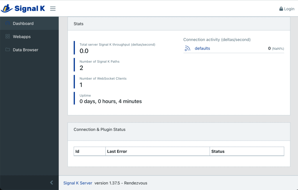
signalk-initial-screen 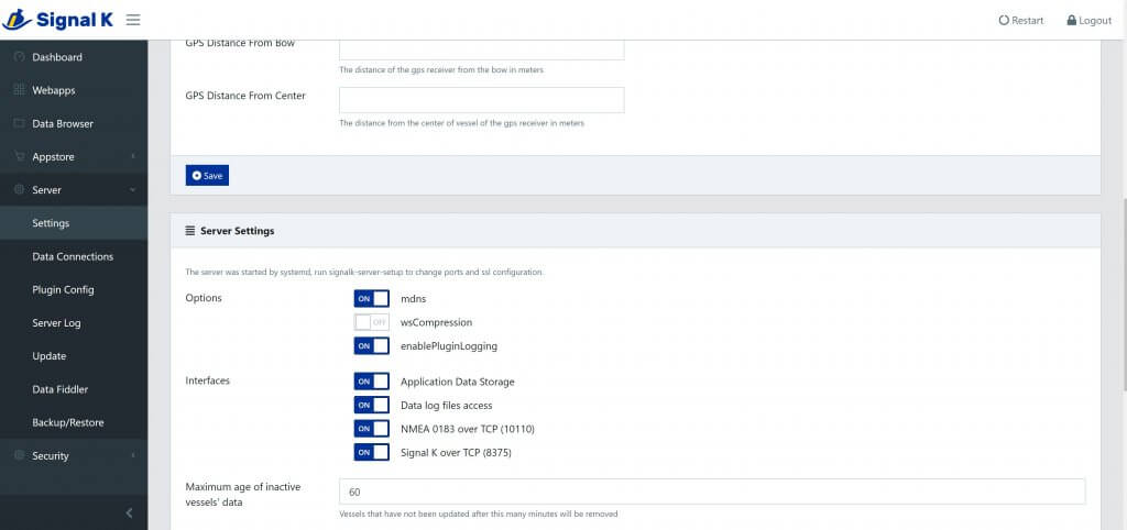
SignalK mDNS setting
If your server has security enabled (it does by default), you should see an access request for your ESP in the Signal K Dashboard, under Security – Access Requests. (You must be logged into the Signal K Server to see the Security sub-menu.) Set the “Authentication Timeout” field to “NEVER”, set the Permission to “Read / Write”, then Approve it. You should start getting data on the Signal K Instrument Panel. (Dashboard – Webapps – Instrument Panel) You can see lots of activity in the Visual Studio Code Serial Monitor, including the connection to the Signal K Server, the request for and approval of the security token, and the flow of data.
If you have any problems with configuring the WiFi credentials, or with SensESP finding your Signal K server, you can hard-code those settings. See Hard-coding Certain Program Attributes.
Once you’ve added it, you’ll need to restart the Signal K server (upper right). You have to do this whenever you make a configuration change to the server or plugin, add a plugin, etc.
Signal K Data Ingestion – Arduino Voltage Level Sensor
So, if everything is working correctly. Now you will see the sensor sending data to the SignalK server. You will seethe data under the data browser. Secondly, you can see in the “Signalk-Dashboard-Data”, screenshot that I’m collecting an additional two inputs (Fuel.1.Tank and Water.1.Tank). This is a sensor that has the ADS1115 Connected. Additionally, you should data being logged. Lastly. I am seeing voltage because the sensor is not grounded.
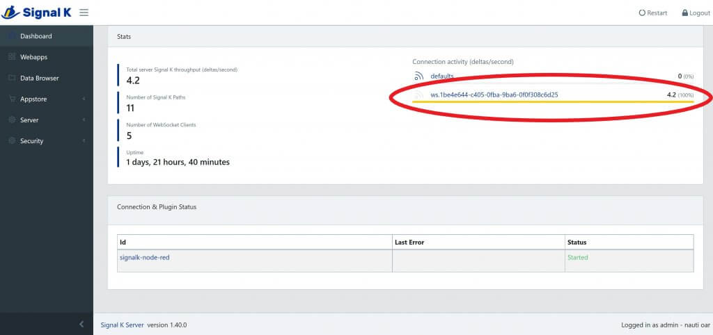
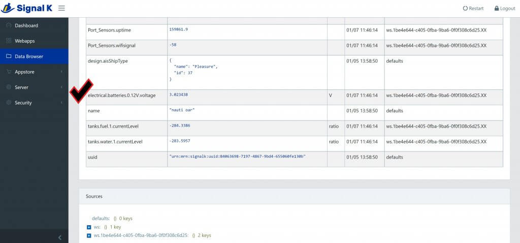
You will also see the ipaddress in the window above, the “Signalk-Dashboard-Data” will list the IP address of the Sensors. In this case, we only have one. You can log into the Sensor and see how it can be configured. Below are screenshots of the data and the device.
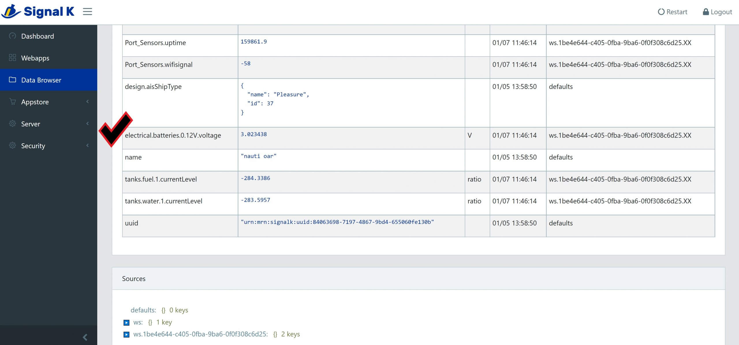
Signalk-Dashboard-Data 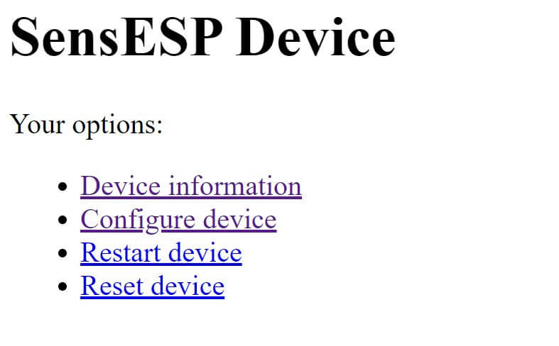
SensESP Sensor
Wrapping things up in this Installment!
What we have up to this point is a functioning installation of the Hardware, Software Components of the SignalK Server and a Sensor sending data to the SignalK server. All of this is running on the bench and working
Arduino Voltage / Fuel Level Sensor – Part Five Conclusion
So what we have up to this point is a functional sensor sending data to the SignalK server and logging data. We still and have yet to install InfuxDB and Grafana.
- ESP-12F Node MCU
- Buck Converter Board 3A
- SignalK Server Installed and Configured and receiving data from a sensor
Additionally, in the next Part of this series. We will configure the ADS1115, add the voltage divider and do some testing before I install this on “Nauti”. When we are done we will read the Battery voltage of Bank One and monitor the Port Fuel Tank Level and display it on the RayMarine Axiom RV 9. So until the next installment, Happy New Year! Hopefully this inspires you build your first sensor and start on working on transforming your boat into a connected boat!